Three-Phase Voltage Unbalance: Calculation, Motor Heating and Derating
Quick answer: calculate NEMA percent voltage unbalance as 100 times the largest deviation from the average of the three line-to-line voltages, divided by that average. Even a small voltage unbalance can cause a much larger current unbalance, extra motor heating and reduced available load.
Worked calculation
Measured voltages are 402 V, 397 V and 391 V.
- Average = (402+397+391)/3 = 396.7 V.
- Deviations are 5.3 V, 0.3 V and 5.7 V.
- Maximum deviation = 5.7 V.
- Unbalance = 100 × 5.7/396.7 = 1.44%.
This result is above 1%, so the cause and motor loading deserve investigation. Do not calculate the percentage as maximum voltage minus minimum voltage divided by average; that is a different metric and produces a different answer.
Why motors run hotter
An unbalanced voltage creates negative-sequence voltage. The resulting negative-sequence magnetic field rotates opposite to the rotor, inducing extra current and loss. The U.S. Department of Energy motor guide explains that current imbalance increases I²R losses in stator windings and rotor bars, raises slip and temperature, and reduces efficiency and winding life.
Derating is not guesswork
NEMA MG 1 includes a motor derating curve for voltage unbalance. DOE guidance notes that more than 1% unbalance requires attention and that motors should not be used above 5% unbalance. Use the current motor manufacturer’s instructions and the applicable NEMA edition; do not interpolate a generic curve for a critical machine without verification.
Where to measure
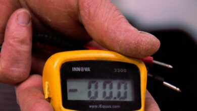
- Measure VAB, VBC and VCA at the motor starter with the motor running and a stable load.
- Repeat at the main distribution board or service entrance.
- Record phase currents, power, power factor and harmonic distortion.
- Repeat after swapping load phases only under an approved isolation plan.
If the service is balanced but the motor control center is not, suspect unequal feeder impedance, loose terminals, damaged contacts, fuse resistance, a failing cable joint or uneven single-phase loads downstream. If both points are unbalanced, involve the supply utility or upstream transformer owner.
Worked loss check
Assume a 30 kW motor draws 52, 57 and 63 A. Average current is 57.3 A and maximum current deviation is 5.7 A, so current unbalance by the same maximum-deviation method is about 9.9%. This does not prove the motor is defective; it shows why a 1.44% voltage unbalance can produce a much larger current asymmetry and why temperature and load should be checked quickly.
Troubleshooting checklist
- Confirm instrument accuracy and simultaneous readings.
- Inspect contactors, disconnects, fuses and terminals for heat and voltage drop.
- Check single-phase load distribution on the same transformer.
- Compare current unbalance at no load and normal load.
- Check motor winding resistance and insulation only after safe isolation.
- Review VFD input-unbalance limits separately; a DC bus does not eliminate rectifier heating.
- Use thermal imaging as supporting evidence, not as the only diagnosis.
FAQ
Is voltage deviation from nameplate the same as unbalance?
No. All three phases can be equally high or low with little unbalance.
Can a VFD fix supply unbalance?
Its output can remain balanced, but the input rectifier and DC-link capacitors may experience extra stress. Follow the drive manufacturer’s limit.
Should I derate immediately at 1.44%?
Compare the result with the current motor standard, manufacturer data, load and temperature. Correct the source whenever practical.
See our guides to motor starting current and voltage drop and industrial motor protection and control.
Sources: DOE motor-driven systems guide and ABB technical note. Photo: Sven Alleblas via Unsplash.