High-voltage power cables incorporate an outer concentric metallic layer, typically comprising a screen, sheath, and/or armour, collectively termed the “sheath.” This component serves several critical functions: providing a path for fault and capacitive charging currents, establishing an earth potential for personnel safety, and acting as a moisture barrier for the insulation system.
For circuits exceedingly approximately 500 A, specialized sheath bonding arrangements are employed to mitigate sheath current losses. Although these configurations incur additional capital and maintenance costs, they frequently enable the use of cables with reduced conductor cross-sections for a given load current. The selected bonding arrangement represents the second most significant factor affecting cable current ratings, subordinate only to the external thermal resistance of the installed environment. Current ratings are determined in accordance with the IEC 60287 series of standards.
A sheath bonding system is essential for insulating protection during normal operation and against transient overvoltage caused by lightning, switching operations, and fault conditions. Furthermore, it fulfills a vital safety role by controlling touch voltages.
This report delineates four principal bonding methodologies: solid bonding, single-point bonding, cross-bonding, and impedance bonding. For extended high-voltage (HV) and extra-high-voltage (EHV) transmission lines, sectionized cross-bonding is the predominant configuration, whereas single-point bonding is typically reserved for shorter circuits.
Sheath Loss Mechanisms
The alternating magnetic field generated by current in the phase conductors induces currents within the metallic sheath via transformer action. These induced currents give rise to two distinct loss components:
- Circulating Current Losses: These occur when the bonding arrangement permits a continuous closed path for sheath current flow. Their magnitude is typically substantial and directly depends on the bonding method.
- Eddy Current Losses: Generated radially and longitudinally within the sheath due to skin and proximity effects, these losses are present irrespective of the bonding configuration but are generally lower in magnitude than circulating currents.
Both loss mechanisms produce ohmic heating within the cable, thereby reducing its ability to carry current. Circulating currents are prevalent in solidly bonded systems and multicore cables with individually sheathed cores. In single-point or cross-bonded systems, circulating currents are eliminated, though eddy current losses persist.
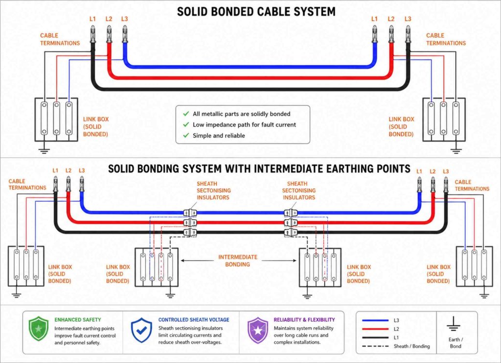
Sheath Bonding Design: Solid Bonding
Methodology
In a solid-bonding arrangement, the cable sheath is connected directly to earth at both ends of the cable route. Intermediate bonding points may also be installed along the route to maintain safety by limiting induced voltages should a terminal bond become disconnected.
Typical Application
This configuration is applied to short cable lengths with lower current ratings, low- and medium-voltage systems (typically up to 66 kV), and submarine cables. Its use in HV transmission systems is generally avoided due to the high losses it entails.
Advantages
- Simplicity and low initial cost.
- Low external magnetic field due to the opposing sheath and conductor currents.
- Minimal maintenance requirements.
- Sheath voltage is maintained at earth potential throughout.
Disadvantages
- Induced circulating sheath currents can reach magnitudes up to 80% of the conductor current.
- Associated Joule heating de-rates the cable system, often necessitating larger conductor sizes to compensate for the capacity reduction.
Key Design Considerations
- Employ dual independent bonding leads at each earthing point to enhance reliability.
- Bonding leads must be sized to withstand prospective fault currents.
- The inclusion of intermediate earthing points is dependent on route length and system parameters.
- The magnitude of the circulating current is independent of the circuit length.
Power Cables Single-Point Bonding in High-Voltage Cable Systems
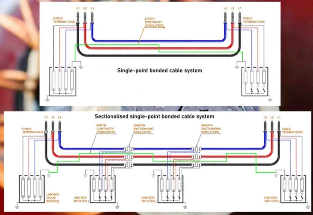
Methodology
Single-point bonding is a cable sheath earthing configuration in which the sheaths of all three phases are interconnected and solidly earthed at one terminal. In contrast, the opposing terminal remains isolated from ground. This method is characteristically applied to circuits of limited length. For extended routes, an adaptation known as multiple single-point bonding is employed. In this scheme, the three sheaths within a defined section are bonded and grounded to an Earth Continuity Conductor (ECC) at one end, while being terminated through Sheath Voltage Limiters (SVLs) at the other. This pattern is replicated sequentially along the cable route.
Application
Single-point bonded systems are widely utilized in high-voltage transmission networks, serving as a principal alternative to multi-point bonding. Their application is particularly prevalent in substation environments with relatively short cable routes where the implementation of cross-bonding is economically non-viable.
Advantages
- Enhanced Current Rating: By eliminating the formation of a closed electrical loop, this method precludes the induction of circulating currents in the sheath. Consequently, associated resistive losses are removed, permitting a higher permissible current rating for the cable conductor.
- Economic Efficiency: The requirement for only a single continuous cable length per phase renders this an economically favorable solution for suitable applications.
- Elimination of Longitudinal Sheath Currents: The absence of a continuous metallic sheath path prevents the flow of longitudinal currents, thereby nullifying circulating current losses. (Note: Non-circulating eddy current losses within the sheath material persist.)
Disadvantages
- Sheath Voltage Rise: A standing voltage is induced longitudinally along the sheath, proportional to the conductor current, cable length, and inter-phase spacing. This voltage increases linearly with distance from the earthed point.
- Cost Implications of Mitigation: To limit this voltage to safe levels, an Earth Continuity Conductor (ECC) must often be installed in parallel with the cable route, introducing significant additional material and installation costs.
- Safety and Insulation Requirement: The isolated sheath end must be meticulously insulated to prevent hazardous exposure to the induced standing voltage, imposing ongoing maintenance obligations.
Design Considerations
The primary design constraint is the sheath standing voltage at the isolated end, which dictates the maximum permissible section length. This voltage must be calculated and limited to a safe touch potential, typically between 35 V and 400 V, as governed by national safety standards.
Effective insulation of the sheath from earth is critical along its entire isolated length. Where anticipated transient overvoltages (e.g., from switching or faults) exceed 75% of the sheath insulator’s Basic Insulation Level (BIL), the installation of a Sheath Voltage Limiter (SVL) between sheath and earth at the open end is mandatory for protection.
An ECC is generally required unless both cable terminals share a common low-impedance earth. To minimize its own induced voltage, the ECC should be centrally transposed with respect to the phase conductors. Its geometric placement relative to the phases must be carefully engineered to ensure effective voltage limitation.
Power Cables Cross-Bonding in High-Voltage Cable Systems
1. Principle and Methodology
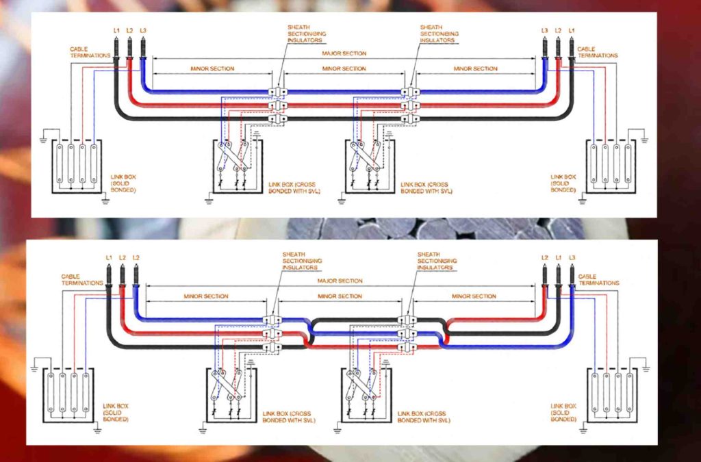
Cross-bonding is a standardized technique employed in three-phase high-voltage cable systems to mitigate power losses within the metallic sheaths. The method exploits the inherent phase relationship (120° displacement) of the induced sheath voltages. Through strategic sectionalization and interconnection of the sheaths, these voltages are vectorially summed, resulting in a near-neutralization of the net electromotive force across a defined major section. This minimization of the resultant voltage drastically reduces circulating sheath currents and associated losses.
Operationally, the cable route is divided into minor sections. The sheaths are then cross-connected at the junctions between these sections—typically transposing the connection sequence (e.g., Phase A sheath to Phase B position)—so that the induced voltages over three successive minor sections sum to approximately zero. These three minor sections constitute one major section. For optimal voltage cancellation, transposition of the cable conductors themselves is recommended, though practical constraints often limit this for large, rigid cables.
2. Configurational Variants
Several implementation schemes exist, tailored to specific installation requirements:
- Continuous Cross-Bonding: Sheaths are cross-bonded at every minor section junction along the entire route. Solid bonding and grounding of all three sheaths together occur only at the two terminal ends of the circuit.
- Sectionalized Cross-Bonding: The route comprises multiple, discrete major sections in series. Sheaths are solidly bonded and earthed at the junctions between major sections and at the circuit ends, while cross-bonding via sheath voltage limiters (SVLs) is employed between minor sections within a significant section.
- Direct Cross-Bonding: Sheath transposition is performed without SVLs or link boxes. This simplifies maintenance by reducing the number of components but complicates disconnection for testing, potentially requiring physical cutting of bonding cables.
- Cross-Bonding of Short Lines: For circuits of intermediate length, a simplified approach using two minor sections with a central cross-bonding point (employing an SVL) is adopted to reduce circulating currents compared to solid bonding.
- Cross-Bonding in Tunnel Installations: Proximity allows for very short bonding leads. Direct cross-bonding is common, and SVLs are typically connected in a delta (rather than star) arrangement. This configuration necessitates SVLs with a higher voltage rating due to elevated induced voltages under normal and transient conditions. Bonding leads must be sized to withstand system short-circuit currents.
3. Applications, Merits, and Demerits
Application: Cross-bonding is the preferred and most prevalent method for longer cable circuits or where high fault currents would lead to excessive sheath voltages under alternative bonding schemes.
Advantages:
- Eliminates the practical length limitation inherent to single-point bonding.
- Significantly reduces sheath circulating currents, lowering losses and permitting higher cable ampacity.
- Provides a continuous, grounded metallic path along the cable circuit, enabling sheath currents to flow during earth faults. This obviates the need for a separate earth continuity conductor (ECC).
- The sheath itself acts as a more effective screening conductor during earth faults than a parallel ECC, thereby reducing induced voltages in adjacent infrastructure.
Disadvantages:
- Increased system complexity and cost.
- Requires careful design to ensure minor sections are of equal length for optimal voltage cancellation—a challenge in practical installations.
4. Key Design Considerations
A fundamental requirement for classic cross-bonding is a minimum of three cable sections (minor sections). Circuits comprising only one or two cable lengths cannot utilize this method and typically default to single-point bonding. Furthermore, residual circulating currents are often present due to inevitable minor imbalances in section lengths and cable spacings.
Permissible induced voltage levels and the voltage differences between sheaths and earth points constrain design. The most severe sheath-to-earth voltages in cross-bonded systems generally arise from two- or three-phase faults. Notably, if a cross-bonded cable circuit is inserted into an overhead line, single-phase faults—particularly with high earth impedances—can generate the highest sheath-to-earth voltages.
Power Cables Impedance Bonding Methodology for Cable Sheaths
Method
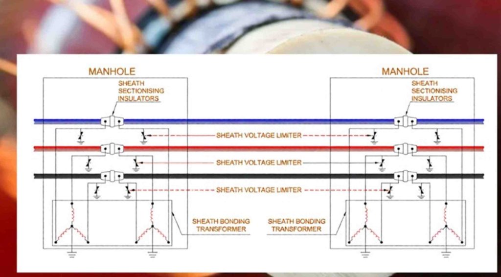
The impedance bonding technique involves the insertion of a defined impedance—such as a reactor or resistor—into the sheath current path. This is performed to limit the magnitude of circulating sheath currents under load conditions and to mitigate fault currents. The impedance may be implemented using standard reactors or more specialized devices, including saturable reactors or bonding transformers.
In the transformer-based sheath bonding configuration, both terminations of each cable sheath are electrically connected to a dedicated three-phase sheath bonding transformer, as illustrated in Figure 7.
Application Context
Impedance bonding methods are generally regarded as less satisfactory than alternative bonding schemes (e.g., cross-bonding, solid bonding) and are not recommended for general application. Their use may be justified in specific, isolated circumstances. For instance, bonding transformers can present an economical solution where suitable phase balancing for cross-bonding is unachievable and single-point bonding is inadmissible—such as in the absence of an empty duct for an earth continuity conductor (ECC). This method may also be employed when a spare cable is installed (e.g., a fourth cable for a single circuit). In such scenarios, reconfiguring a cross-bonding system upon deployment of the spare cable is a complex and time-intensive operation, whereas reconnection within a bonding transformer scheme is comparatively simple.
Advantages
A principal advantage of the bonding transformer scheme is its efficacy in limiting induced sheath circulating currents, irrespective of whether the spacing between cable joint bays (vaults) is equal or unequal.
Disadvantages
The method introduces several disadvantages:
- It requires additional physical space within cable vaults to accommodate the impedance devices.
- The requisite impedance devices are relatively costly, as their design must account for and withstand prospective fault current conditions.
- Under normal operating conditions, third-harmonic currents can be induced into the sheath, posing a risk of interference to adjacent telecommunication lines.
- Stray direct currents, which may enter the system via grounding connections, can lead to saturation of the magnetic iron cores within the reactors or transformers, thereby disrupting their intended operation.
Design Considerations
Key design considerations for impedance bonding include:
- Impedance devices are typically furnished with center taps or designated grounding points to facilitate connection to earth.
- Sheath bonding transformers must be specifically designed to avoid core saturation under the influence of sheath voltages induced by both normal and short-term emergency operating currents.
- Cable sheaths are additionally connected to local earth through sheath voltage limiters (SVLs) to control transient overvoltages.
Conclusion
Sheath bonding constitutes a critical design aspect for high-voltage power cable transmission systems, demanding careful engineering analysis. The selected bonding method fulfills multiple essential functions and exerts a substantial influence on both the total