Demystifying Motor Control Circuits: How Industrial Motors Start Safely
If you’ve ever noticed the lights flicker when a heavy appliance kicks on, you’ve witnessed the raw power demands of an electric motor. In industrial settings, where alternating current (AC) motors drive everything from conveyor belts to massive pumps, managing this initial power surge is critical. Without intervention, large motors can draw a massive inrush current during startup—often 5 to 8 times their normal running current. This can cause severe voltage drops across the local power grid and subject the motor’s internal windings to damaging thermal and mechanical stress.
To bridge the gap between high-power startup demands and efficient steady-state operation, engineers rely on motor control circuits. Let’s explore the mechanics behind the three most common types of motor starters used in modern engineering.
1. Direct On-Line (DOL) Starter: The Direct Approach
The Direct On-Line (DOL) starter is the simplest and most straightforward method for controlling an AC motor. As the name implies, it connects the motor’s stator windings directly to the main power supply.
How it Works
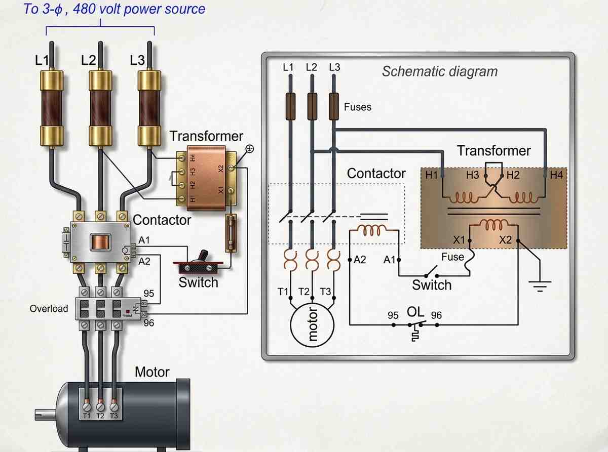
Because it applies the full line voltage immediately, the DOL starter offers no reduction in starting current. To protect the system from electrical faults, it relies heavily on integrated protective components:
- Circuit Breakers & Fuses: Configured to immediately interrupt the connection if the current exceeds the motor’s rated threshold.
- Overload Protection: Thermal relays monitor the heat generated by the current, cutting power if the motor struggles or stalls.
Applications & Limits
Due to the massive, unregulated inrush current, DOL starters are strictly limited to smaller applications—typically motors with power ratings under 10 kW. Using them on larger machinery would risk destabilizing the local electrical grid.
2. Star-Delta Starter: The Mathematical Compromise
For medium to large-sized induction motors, the Star-Delta starter offers an elegant, cost-effective way to reduce starting current without the need for expensive external voltage regulators. This method is specifically designed for motors configured to operate in a Delta connection under normal conditions.
The Two-Stage Process
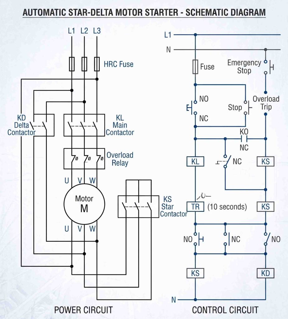
The starter utilizes six accessible terminals from the stator windings to automatically transition the motor through two distinct phases:
- The Star Phase (Starting): The control circuit initially connects the stator windings in a Star (Y) configuration. Mathematically, this reduces the voltage across each motor phase by a factor of √3 (approx. 58% of line voltage). Consequently, the starting line current drops to just 1/3 (33%) of what it would be during a DOL Delta start.
- The Delta Phase (Running): Once the motor accelerates to a safe running speed, a timer triggers a set of contactors to rapidly switch the windings into a Delta configuration, restoring full line voltage so the motor can operate at maximum efficiency.
3. Auto-Transformer Starter: Custom Voltage Control
When dealing with high-capacity industrial motors—typically those above 80 kW—the rigid 1/3 current reduction of a Star-Delta starter isn’t always sufficient. Enter the Auto-Transformer Starter, a highly flexible but more complex solution.
Anatomy of the System
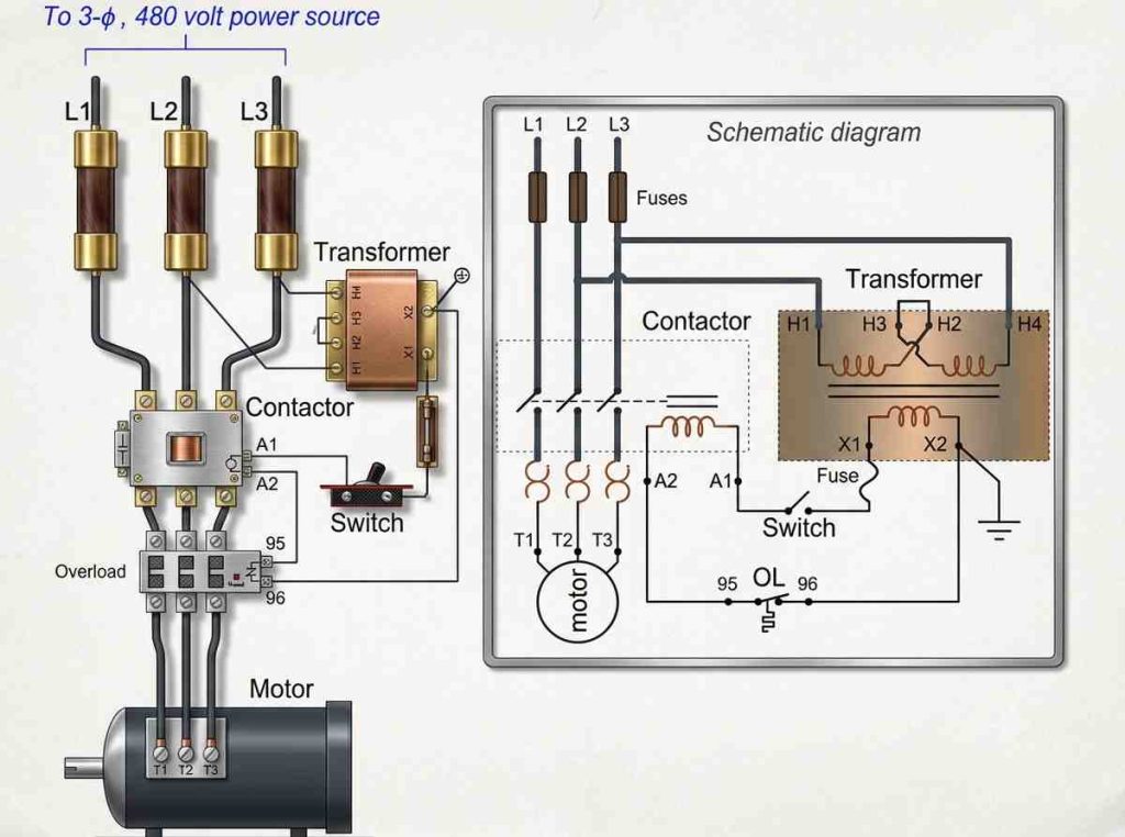
This control assembly is a robust ecosystem consisting of:
- A 3-phase tapped autotransformer
- An arrangement of contactors (switching mechanisms)
- Power fuses and a thermal overload block are wired in series with the contactor coil to ensure automatic shutdown during a thermal fault.
The Switching Sequence
The autotransformer uses voltage taps (e.g., 50%, 65%, or 80% of line voltage) to smoothly ramp up the motor. The sequence unfolds in precise steps:
[Star Contactor Energizes]
          │
          ▼
[Transformer Contactor Energizes] ──► (Motor starts at a safe, reduced voltage)
          │
          ▼
[Time Delay / Acceleration]
          │
          ▼
[Main Contactor Energizes] ─────────► (Motor receives full load/line voltage)
          │
          ▼
[Transformer Contactor De-energizes]
By stepping down the initial voltage through the transformer, the starting current and torque are kept strictly within safe operating parameters. Once the motor stabilizes, it is switched directly to the main lines, and the transformer is isolated to save energy.
Choosing the Right Starter
Selecting the ideal motor control circuit is a balancing act between motor size, cost, and grid stability.
| Starter Type | Typical Power Range | Cost | Core Mechanism |
| Direct On-Line (DOL) | Low (<10 kW) | Low | Direct connection to full line voltage. |
| Star-Delta | Medium to Large | Moderate | Reconfigures windings to reduce voltage by √3 |
| Auto-Transformer | Very High (>80 kW) | High | Uses a tapped transformer for variable voltage reduction. |
Understanding these circuits is fundamental to modern automation, ensuring that the heavy machinery driving our industries can start up safely, predictably, and without blowing the system’s fuses.