Electrical Protection Study Course: A Six-Week Practical Roadmap
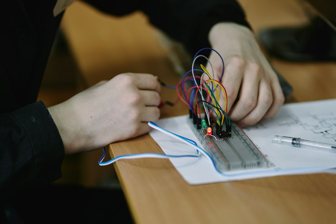
Quick answer: Learn protection in the order the system operates: model sources and faults, understand instrument transformers, study each protection function, coordinate time and current, then test the implemented logic. This six-week roadmap produces one auditable mini-project instead of disconnected notes.
Course outcome
By the end, the learner should be able to build a simple single-line model, calculate representative maximum and minimum faults, select CT inputs, explain common relay functions, create a time-current coordination plot, draft a setting sheet and plan commissioning tests. This is education, not authorization to alter live protection.
Week 1: system model and fault current
- Per-unit quantities, source impedance and transformer impedance.
- Maximum and minimum three-phase and earth faults.
- Utility, generator, bus-tie and maintenance operating states.
- Equipment interrupting and short-time withstand.
Deliverable: a controlled single-line diagram and fault-level table with assumptions.
Week 2: CTs, VTs and measurement limits
- Ratio, polarity, burden and accuracy.
- CT saturation during through faults.
- Residual and neutral current arrangements.
- Scaling primary quantities into relay inputs.
Exercise: calculate secondary current for normal load and two fault cases, then identify where saturation could affect differential or overcurrent protection.
Week 3: overcurrent and earth-fault protection
Study pickup, definite time, inverse curves, instantaneous elements and grading margins. Plot the load, cable damage limit, downstream device and upstream relay on common axes. Include curve tolerances and breaker clearing time.
Deliverable: one coordinated feeder pair for utility and generator modes.
Week 4: transformer, motor and bus protection
- Transformer differential restraint, vector compensation and inrush behavior.
- Restricted earth fault and backup overcurrent.
- Motor thermal, locked-rotor and unbalance protection.
- Bus differential zones and CT requirements.
Compare what each element detects and what it intentionally ignores. Protection security is as important as sensitivity.
Week 5: line and system protection
- Distance zones, reach and time delay.
- Directional overcurrent for meshed or parallel paths.
- Breaker-failure initiation and bus trip logic.
- Under/overvoltage and frequency functions where applicable.
Exercise: draw a logic diagram showing trip, intertrip, breaker failure and lockout boundaries.
Week 6: settings, arc flash and commissioning
Convert the study into an approved setting record. Check the effect of clearing time on incident energy, then plan secondary injection, primary injection where required, trip-circuit checks, end-to-end tests and restoration controls.
Mini-project data set
Use a simple 11 kV/0.4 kV transformer feeding a main LV board with two outgoing feeders. Provide source fault level, transformer impedance, conductor ratings, breaker models and two operating modes. The learner must:
- calculate LV fault levels;
- select pickup values within conductor and load limits;
- coordinate one outgoing breaker with the main;
- explain transformer inrush treatment;
- draft a test sheet with expected results.
Weekly study rhythm
Use three sessions: concept, worked calculation and verification. Keep a calculation notebook with source, equation, units, assumptions and independent check. Redraw manufacturer curves rather than guessing values from a screenshot.
Assessment rubric
| Area | Evidence |
|---|---|
| Accuracy | Correct units, ratios and fault cases |
| Coordination | Clear margins and device tolerances |
| Traceability | Source and revision for every setting |
| Safety | No change without approval and test control |
| Communication | Readable SLD, curves and setting sheet |
FAQ
Which software is required?
A spreadsheet and curve plotting are sufficient for the learning model. Commercial tools help with large systems but do not replace engineering understanding.
Can the sample settings be used on a real project?
No. Real settings require exact network data, device manuals, standards and formal approval.
What should be studied next?
Move to communication-assisted schemes, IEC 61850 logic, disturbance-record analysis and end-to-end testing.
Course reading path
- Relay coordination study
- LSIG settings guide
- Transformer inrush troubleshooting
- Arc-flash clearing time