Transformer Inrush Troubleshooting: Nuisance Trips and Field Checks
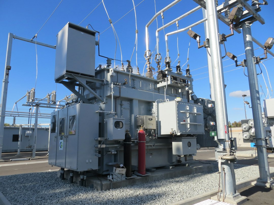
Transformer energization can produce a short, asymmetric current many times the rated current. Treating this normal transient as a fault causes nuisance trips; ignoring it can weaken genuine protection.
Photo by American Public Power Association on Unsplash.
Why this topic matters
Good engineering decisions connect calculations with site conditions, equipment data and operating scenarios. The workflow below is intended for preliminary design, technical review and commissioning preparation. It does not replace the current local code, utility rules or a competent professional’s approval.
Core engineering checks
- Residual core flux and the point on the voltage wave determine the first-cycle peak.
- Second-harmonic restraint is commonly used to distinguish inrush from internal faults.
- Upstream breakers and fuses need time-current settings that ride through expected energization.
- Sequential energization and controlled switching can reduce system voltage dips.
Calculation starting point
Start with rated current I = S/(√3 × V) for a three-phase transformer. Plot the manufacturer’s inrush envelope and damage curve on the same time-current chart as the proposed protective devices.
Recommended workflow
- Collect evidence: obtain drawings, interval data, nameplates, manufacturer curves and site measurements.
- Define scenarios: include normal operation, peak demand, maintenance states, credible faults and future expansion.
- Calculate: state assumptions, units, correction factors and the source of every input.
- Coordinate: check interfaces with protection, controls, communications, civil works and operations.
- Verify: turn each design assumption into an inspection, measurement or functional test.
Europe and Gulf considerations
Weak islanded grids, generator-backed facilities and long Gulf distribution feeders can experience deeper voltage dips. Confirm assumptions using manufacturer data and the actual source impedance.
Common mistakes
- Using nominal ratings without environmental or installation derating.
- Checking only one operating condition.
- Relying on software output without validating inputs and boundary conditions.
- Leaving commissioning criteria undefined until the equipment arrives.
- Failing to record the final settings, firmware, drawings and test results.
Handover checklist
Keep the approved design basis, calculations, single-line or network diagram, equipment schedules, protection and control settings, inspection records, test certificates, operating instructions, maintenance intervals and an as-built change log. A useful handover package allows a future engineer to understand not only what was installed, but why.
Frequently asked questions
Can this method be used for final design?
It is a strong review framework, but final values must come from project-specific data and the current requirements of the responsible authority.
What should be verified first?
Verify the input data that most strongly changes safety or capacity: source strength, load profile, environment, installation method and protective-device characteristics.
How should uncertainty be handled?
Use conservative but explicit assumptions, test sensitivity to uncertain inputs, and replace assumptions with measurements during commissioning.
Explore more practical guides in our engineering library and English Engineering section.