LSIG Trip Unit Settings: A Practical Coordination Guide
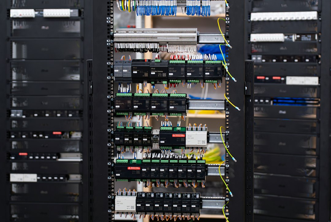
LSIG settings should never be chosen from a generic table. They are the output of a protection-coordination study that considers the actual breaker, conductor limits, maximum and minimum fault current, downstream devices, starting currents and every normal operating mode. This guide explains the engineering logic behind each function and shows how to review a proposed setting without turning an example into a project setting.
What does LSIG mean?
An electronic trip unit may provide some or all of four protection functions:
| Function | Purpose | Typical adjustable quantities |
|---|---|---|
| L — Long-time | Overload protection | Pickup and inverse-time delay |
| S — Short-time | Selective protection for lower short-circuit currents | Pickup, delay and sometimes I²t ON/OFF |
| I — Instantaneous | Rapid clearing of high short-circuit current | Pickup; no intentional coordination delay on many units |
| G — Ground fault | Equipment ground-fault protection | Pickup and delay, subject to the grounding arrangement |
Manufacturers use different symbols, reference currents and setting ranges. One unit may express short-time pickup as a multiple of the long-time pickup, while another uses sensor or rated current. Always translate every dial position into amperes and seconds using the manual for the exact trip-unit catalog number.
Collect the study inputs before touching a dial
- The approved single-line diagram and all source configurations: utility, generator, bus tie, transformer parallel operation and maintenance bypasses.
- Calculated load current and credible growth, plus conductor ampacity after temperature, grouping and installation derating.
- Maximum fault current for interrupting and withstand checks, and minimum fault current for sensitivity.
- Downstream fuse, MCCB, motor-protection and relay curves, including tolerances and total clearing time.
- Transformer magnetizing inrush, motor starting current, UPS input behavior and other legitimate transient currents.
- Breaker frame, sensor/rating plug, trip-unit firmware, neutral arrangement, ground-fault sensing method and manufacturer coordination tables.
- Equipment short-time withstand, cable thermal limit and the arc-flash model for each switching state.
A setting sheet without these inputs is a list of numbers, not a protection study.
1. Long-time pickup and delay
The long-time pickup must carry the intended load yet protect the conductor and connected equipment. The practical boundary is not merely the breaker frame rating: the complete current path may be limited by the cable, busbar, terminals, enclosure temperature or local installation rules.
Illustrative check: suppose a 630 A trip unit feeds a design load of 420 A and the protected conductor has an allowable current of 500 A after all derating. A nominal pickup of 0.80 × 630 = 504 A would slightly exceed that conductor limit, so it cannot be accepted just because the dial offers 0.80. The engineer must choose an available pickup at or below the permitted limit that still carries the design load, then verify the associated delay against overload withstand and downstream curves. Actual dial steps vary by product.
Thermal memory also matters. A breaker may remember recent heating and trip faster after a prior overload. Record whether the study and commissioning test include this behavior.
2. Short-time pickup and delay
Short-time protection creates a controlled coordination window. Its pickup should remain above legitimate downstream transients and the operating region of the downstream device, while staying low enough to detect the minimum short-circuit current in its zone. Its delay gives the downstream breaker time to clear first.
- At high fault current, confirm that the upstream short-time delay does not exceed switchgear, busbar or conductor withstand.
- At low fault current, confirm that the element still picks up in generator operation or at the remote end of a long feeder.
- Include breaker opening and total clearing time, not only the trip-unit timer.
Some units offer I²t ON, producing an inverse-time portion, and I²t OFF, producing a definite-time characteristic over the applicable range. The correct choice depends on downstream curves, the approved manufacturer data and any zone-selective interlocking scheme.
3. Instantaneous pickup
Instantaneous protection reduces energy by clearing severe faults rapidly, but an upstream instantaneous element set too low can defeat selectivity. Set it only after plotting the downstream instantaneous region, transformer or motor inrush and calculated fault-current range.
Do not disable or raise instantaneous pickup merely to stop nuisance trips. First identify the operating element from the event record and test whether the cause was inrush, CT behavior, an incorrect setting group or a real fault. If instantaneous protection is intentionally omitted for coordination, the short-time withstand and arc-flash consequences require explicit verification.
4. Ground-fault pickup and delay
Ground-fault settings depend on how current is measured and how the system is grounded. Residual summation, a neutral sensor and source-ground sensing are not interchangeable. Check sensor polarity, neutral conductor treatment, parallel paths and whether normal leakage or harmonics can influence the measurement.
The pickup must be sensitive enough for the minimum ground fault in the protected zone without operating on normal unbalance or leakage. The delay must coordinate with downstream ground-fault protection while remaining inside equipment and conductor damage limits. Ground-fault protection on the main breaker does not replace personnel-protection RCDs where those are required.
I²t and zone-selective interlocking
Zone-selective interlocking (ZSI) links downstream and upstream trip units. For a downstream fault, the downstream device sends a restraint signal so the upstream device observes its coordinated delay. For a fault seen only by the upstream device, the absence of restraint allows faster clearing. This can preserve selectivity while reducing stress, but it depends on correct wiring, compatible devices, settings and functional testing.
Manufacturer guidance is product-specific. For example, Schneider documentation notes that short-time and ground-fault functions can participate in ZSI and gives explicit restrictions for zero-delay and I²t selections. Treat these as design inputs for the applicable equipment, not universal rules for every brand.
A review table for the coordination study
| Check | Question to answer | Evidence |
|---|---|---|
| Load | Will normal load and credible starting current remain below pickup? | Load schedule and starting study |
| Conductor | Does long-time protection stay within the derated conductor limit? | Ampacity calculation and terminal rating |
| Selectivity | Does the downstream device clear first through the required fault range? | Time-current curves and tested coordination tables |
| Sensitivity | Will each element detect the minimum fault in every source mode? | Minimum-fault calculation |
| Withstand | Is total clearing time below equipment and cable limits? | Short-time withstand and damage curves |
| Arc flash | How do the settings change clearing time and incident energy? | Arc-flash study for all operating modes |
| Commissioning | Were installed ratios, settings, wiring and trip operation verified? | Primary/secondary injection and signed setting record |
Commissioning checklist
- Match breaker, sensor, rating plug and trip-unit model to the approved study.
- Convert every multiplier into primary amperes and document the reference current.
- Confirm the active setting group and any password or seal control.
- Verify neutral and ground-fault sensor wiring, polarity and ratio.
- Test pickup, timing, trip output and breaker operation using the approved manufacturer procedure.
- Function-test ZSI wiring and alarm logic where installed.
- Save event records and final settings, then update the single-line diagram and coordination report.
- Control later changes: a larger cable, new generator or different breaker can invalidate the study.
Europe and Gulf project notes
IEC 60947-2:2024 covers low-voltage circuit-breakers within its stated voltage scope, but a compliant breaker still needs project-specific coordination and local approval. European and Gulf projects may add utility rules, civil-defense requirements, client specifications and local wiring regulations. High ambient temperature can also reduce cable or enclosure capacity; do not “compensate” by raising a protection setting without recalculating the protected system.
Related engineering guides
- Relay coordination study and time-current curves
- Arc-flash risk: fault current and clearing time
- Low-voltage switchboard design and verification
- Transformer inrush troubleshooting and field checks
Technical references
- Schneider Electric: meaning of LSIG protection functions
- Schneider Electric: ComPacT NS MicroLogic A/E user guide
- ABB: standard LI, LSI and LSIG protections
- IEC 60947-2:2024 — low-voltage circuit-breakers
Engineering notice: This article is educational. Final settings must be calculated, reviewed and commissioned by qualified personnel using the exact equipment data, applicable standards and the approved protection study.