Guide to Installing a Low Voltage Dry-Type Transformer
Installing a low-voltage dry-type transformer correctly is essential for safety, reliability, and long-term performance. Whether you’re replacing an existing unit or installing a new one for the first time, following a structured process helps prevent costly mistakes and downtime. In this guide, we’ll walk through the basic installation process for a three-phase, general-purpose dry-type transformer — from safety checks and tap settings to grounding and final testing.
Important Installation Warning
This article is intended as a general installation guide only. Always follow the manufacturer’s installation manual, transformer nameplate data, local electrical codes, and all applicable laws and regulations. This guide focuses specifically on the physical installation of the transformer and assumes that proper disconnects and overcurrent protection are already in place. Transformer installation and removal should only be performed by a qualified electrical professional.
Dry-Type Transformer Installation Process
1. Start With Safety Checks
Before beginning any transformer work, take a few critical safety precautions.
Wear Proper PPE
Always use the appropriate personal protective equipment (PPE), including:
- Safety gloves
- Eye protection
- Arc-rated clothing
- Any site-specific safety gear
Verify Incoming Voltage
Measure and record the service voltage feeding the transformer. You’ll use this reading later when setting the primary voltage taps.
De-Energize and Lock Out the Circuit
If replacing an existing transformer:
- Shut off the feeder circuit
- Apply lockout/tagout procedures
- Verify zero voltage before touching any conductors
Safety should always come first.
2. Gather the Required Tools
Having the right tools ready will make the installation smoother and safer.
Typical tools include:
- Lockout/tagout equipment
- Socket set
- Torque wrench
- Drill
- Concrete anchors
- Hole punch or knockout set
- Grounding lugs and conductors
- Razor knife or wire brush
- Level
- Tape measure
3. Remove the Existing Transformer (If Applicable)
If this is a replacement project, carefully remove the old transformer.
Disconnect the Transformer
After verifying the unit is de-energized:
- Remove the front panel
- Disconnect the conductors in this order:
- Primary conductors
- Secondary conductors
- Grounding and bonding conductors
Following this sequence helps reduce the risk of accidental contact or induced voltage issues.
Remove the Old Unit
- Unbolt the transformer from its anchors
- Remove the unit from the installation area
If this is a brand-new installation, you can skip directly to the next step.
4. Inspect the New Transformer
Once the new transformer is unpacked and removed from the pallet, inspect it thoroughly before installation.
Review the Nameplate
Verify the transformer matches the system requirements, including:
- kVA rating
- Primary voltage
- Secondary voltage
- Phase
- Frequency
Check Ventilation Clearance Requirements
Dry-type transformers rely on airflow for cooling, so proper clearances are critical.
NEC Article 450 typically requires:
- Minimum 6 inches clearance on all sides
- At least 36 inches of clearance in front
Also verify:
- Airflow is unobstructed
- Primary and secondary terminals are accessible
- Conduit entry locations work for your installation
5. Position and Anchor the Transformer
Move the transformer into its final position carefully.
Level the Unit
Use a level to ensure the transformer sits evenly. An uneven transformer can create unnecessary vibration and noise.
Install Vibration Pads (Optional)
If noise reduction is a concern, vibration isolation pads can help reduce humming and mechanical vibration.
Secure the Transformer
- Remove old anchors if necessary
- Drill new anchor holes
- Install concrete anchors
- Bolt the transformer securely to the floor
A properly anchored transformer improves both safety and stability.
6. Adjust the Voltage Taps
Next, verify the primary tap settings.
Review the Tap Diagram
Remove the enclosure panel and locate the transformer tap diagram on the nameplate.
Most transformers ship configured on the nominal tap setting, which is commonly the middle position.
Compare to Measured Voltage
Use the voltage reading you recorded earlier to determine whether tap adjustments are needed.
Adjust the Taps if Necessary
Before making any changes:
- Ensure the transformer is completely de-energized
- Remove varnish from tap terminals if needed
- Move jumper leads to the correct tap positions
- Tighten all connections to manufacturer torque specifications
Never change transformer taps while energized.
Reduce Transformer Noise (Optional)
Some installers slightly loosen the internal isolation pads to reduce operating noise after energization.
7. Create Knockout Openings
Next, prepare the enclosure for conduit and cable entry.
Use Factory Knockouts When Possible
If factory knockouts are available, use them to maintain enclosure integrity.
Otherwise:
- Create openings using a hole punch or knockout set
- Route conductors into the enclosure
- Attach flex conduit or conduit fittings securely
Clean conduit routing improves airflow and simplifies future maintenance.
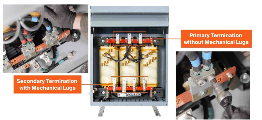
8. Connect Primary and Secondary Conductors
With conductors in place, begin making terminations.
Verify Conductors First
Before terminating:
- Confirm conductor sizing matches the transformer rating
- Verify phase configuration
- Check conductor identification
Make the Connections
Connect conductors in the correct sequence:
- Primary conductors to primary terminals
- Secondary conductors to secondary terminals
Use properly sized mechanical compression lugs where required.
Finalize Connections
- Apply an anti-oxidant compound (such as Noalox®) when needed
- Torque all connections to manufacturer specifications
- Keep wiring clear of ventilation openings
Proper terminations are essential for preventing overheating and future failures.
9. Grounding and Bonding
Grounding is one of the most important parts of transformer installation.
Under NEC 250.30, separately derived systems typically require the transformer neutral (X0) to be solidly grounded.
Install Grounding Connections
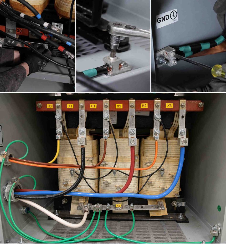
If a neutral terminal is present:
- Install grounding lugs
- Bond the neutral bus appropriately
- Route grounding electrode conductors into the enclosure
Ensure Solid Metal-to-Metal Contact
Where grounding lugs are mounted:
- Remove paint from the enclosure surface
- Ensure solid bonding contact
Finally:
- Terminate all equipment grounding conductors
- Verify grounding conductor sizing meets code requirements
10. Final Assembly and Testing
Before energizing the transformer, perform a complete final inspection.
Verify the Installation
Confirm:
- All connections are tight
- Grounding is complete
- Clearances are maintained
- Conductors are secure
- No tools or debris remain inside the enclosure
Energize the Transformer
Once everything is verified:
- Remove lockout/tagout devices
- Energize the transformer
- Listen for abnormal noise or vibration
- Verify proper secondary voltage
If the output voltage is outside the acceptable tolerance, de-energize the transformer and adjust the primary taps accordingly. Finally, reinstall the front panel.
Conclusion
Installing a dry-type transformer isn’t overly complicated, but it does require careful attention to detail. Proper grounding, secure terminations, correct tap settings, and adequate ventilation all play a major role in ensuring safe and reliable operation. Taking the time to install the transformer correctly helps reduce failures, improve efficiency, and extend the life of the equipment.