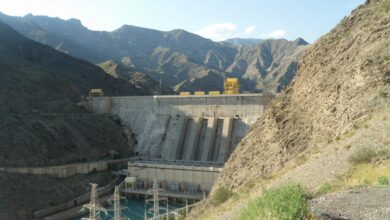
Penstock Water Hammer: Pressure Rise, Valve Closing and Surge Checks
Water hammer in a penstock is a transient pressure wave created when flow velocity changes faster than the water-and-pipe system can respond. A rapid turbine wicket-gate or main-inlet-valve closure can produce a high positive pressure; rapid opening, load acceptance, drainage, or poor venting can create damaging low pressure. A safe design therefore checks both maximum and minimum hydraulic grade lines, not only static head.
Quick engineering workflow
- Define every operating and emergency transient: load rejection, load acceptance, normal stop, emergency valve closure, runaway, pump trip, filling, and drainage.
- Calculate steady-state flow, velocity, static head, and friction losses.
- Estimate wave speed and the critical reflection time 2L/a.
- Use the Joukowsky relation for a conservative rapid-closure screening check.
- Compare the actual closure law with the critical time.
- Run a method-of-characteristics or equivalent transient model for the complete waterway.
- Check penstock, valve, turbine, bifurcation, anchors, supports, surge equipment, and air valves against maximum and minimum pressure envelopes.
- Validate settings during controlled commissioning with calibrated fast-response pressure measurements.
The two first-pass equations
For a rapid velocity change, the classical Joukowsky relation provides an initial maximum pressure-rise estimate:
ΔH = a × ΔV / g
ΔP = ρ × a × ΔV
Tcritical = 2L/a
Here, ΔH is head change, ΔP is pressure change, a is pressure-wave speed, ΔV is the destroyed flow velocity, g is gravitational acceleration, ρ is water density, and L is the distance between the control device and the effective upstream reflection point. If the relevant velocity change occurs in a time shorter than roughly 2L/a, it behaves as a rapid closure. The Bureau of Reclamation’s penstock monograph uses this same criterion and states that maximum design pressure combines static head and water-hammer head.
Worked example: 800 m penstock and a 3 m³/s load rejection
Consider a steel penstock with length 800 m, internal diameter 1.20 m, flow 3.0 m³/s, static head at the turbine of 120 m, and an estimated elastic wave speed of 1,000 m/s. The example is for screening only; final wave speed must include pipe diameter, wall thickness, elastic modulus, restraint, water compressibility, lining, and entrained air.
| Step | Calculation | Result |
|---|---|---|
| Flow area | π × 1.20² / 4 | 1.131 m² |
| Initial velocity | 3.0 / 1.131 | 2.65 m/s |
| Critical time | 2 × 800 / 1,000 | 1.60 s |
| Rapid-closure head rise | 1,000 × 2.65 / 9.81 | 270 m |
| Pressure rise | 1,000 × 1,000 × 2.65 | 2.65 MPa ≈ 26.5 bar |
| Preliminary total head | 120 + 270 | 390 m ≈ 38.3 bar |
If the full velocity were removed in less than 1.6 s, the screening result is severe: the water-hammer head is more than twice the static head. The correct conclusion is not automatically “make the penstock 38.3-bar rated.” Instead, the team must model the real wicket-gate or valve closing curve, turbine boundary condition, friction, reservoir response, pipe elasticity, and reflections, then evaluate whether slower closure, governor cushioning, a surge tank, relief device, or another mitigation is required.
What changes when closure is slower?
For a simplified rigid-column screening calculation with a linear closure time longer than 2L/a, an approximate head rise is:
ΔH ≈ 2L × ΔV /(g × Tc)
With an 8 s closure, the example gives about 54 m of head rise, so static plus transient head is approximately 174 m, or 17.1 bar. This illustrates why closure timing matters, but it is not a final design result. Real valves do not produce a velocity change proportional to stroke: the last part of travel can remove a large fraction of remaining flow, and maximum pressure may occur during partial closure. Reclamation notes that maximum rise depends on the rate of velocity change and that governor timing must have a specified minimum permissible closing time.
Wave speed is not simply 1,400 m/s
The acoustic velocity in unrestricted water is high, but an elastic steel pipe expands under pressure, lowering the effective wave speed. Thinner walls, larger diameter, flexible restraints, liners, and entrained air can reduce it further. Because ΔH is proportional to a, wave speed strongly affects the Joukowsky result. Yet a lower wave speed also increases the reflection time 2L/a and changes resonance, governor interaction, and pressure-wave timing. Obtain the value from a validated pipe-and-fluid model rather than choosing a convenient constant.
Pressure scenarios the transient model must include
| Scenario | Typical concern | Boundary condition to verify |
|---|---|---|
| Full-load rejection | High pressure and overspeed | Governor law, wicket-gate closure, turbine characteristic |
| Emergency main valve closure | Maximum local surge | Fastest credible valve curve and actuation failure modes |
| Rapid load acceptance/opening | Low pressure and column separation | Minimum reservoir level and maximum opening rate |
| Pump trip or power failure | Flow reversal and check-valve slam | Rotating inertia, pump four-quadrant curve, valve dynamics |
| Filling and drainage | Air pocket compression or vacuum collapse | Air-valve capacity, vent location, operator sequence |
| Emergency gate closure | Vacuum downstream of gate | Air demand and venting capacity |
The U.S. Army Corps of Engineers requires penstocks to be designed for static head plus water hammer and calls for transient studies along the conduit. It also identifies load rejection, load acceptance, runaway, and emergency closure as relevant cases. Reclamation research warns that inadequate air admission during emergency gate closure can create negative pressure capable of irregular gate operation or penstock collapse.
Why maximum pressure is only half the problem
- Sub-atmospheric pressure: may buckle a thin or embedded liner if external pressure exceeds internal pressure.
- Column separation: vapor cavities can form and later collapse, causing a second high pressure spike.
- Air pockets: trapped air changes wave speed and can compress violently.
- Check-valve slam: reverse velocity at closure can create a severe local surge.
- Resonance: repeated reflections may couple with governor or valve oscillation.
- Anchor loads: transient pressure and momentum changes create longitudinal forces at bends, valves, branches, and reducers.
Mitigation options and their trade-offs
| Measure | Benefit | What must be checked |
|---|---|---|
| Slower or shaped closure | Reduces rate of velocity change | Overspeed, stopping time, final-stroke flow characteristic |
| Governor cushioning | Controls final gate movement | Failure case with cushioning inoperative |
| Surge tank/shaft | Provides a nearby free-surface buffer | Oscillation, tank size, overflow, minimum level |
| Air vessel | Supplies/absorbs transient volume | Gas volume, precharge, maintenance, membrane condition |
| Pressure-relief valve | Limits positive pressure | Opening speed, capacity, discharge route, chatter |
| Air/vacuum valve | Limits negative pressure during drainage or separation | Inflow/outflow capacity, contamination, slam |
| Flywheel/rotating inertia | Slows pump or turbine speed change | Mechanical stresses and operating response |
For the steady-state energy context behind flow and head, see our pumped-storage hydropower sizing example and hydropower mechanics overview.
Model review checklist
- Geometry, elevations, diameters, wall thicknesses, materials, linings, and restraint conditions match as-built data.
- Reservoir maximum/minimum levels and tailwater boundary are correct.
- Steady-state model reproduces measured head losses and flows.
- Valve and wicket-gate curves use discharge versus travel, not only actuator stroke versus time.
- Turbine or pump four-quadrant behavior is represented where reversal is possible.
- Numerical time step and reach length satisfy the method’s stability and wave-travel requirements.
- Vapor pressure/cavitation and column-separation treatment are documented.
- Normal, emergency, single-failure, and loss-of-power cases are run.
- Pressure envelopes are compared with allowable internal and external pressure at every station.
- Sensitivity cases cover wave speed, friction, closure time, air content, and device availability.
Commissioning checks
- Calibrate fast-response pressure transducers and synchronize them with governor, valve, speed, power, and position signals.
- Verify valve and wicket-gate travel times, including the final cushioning segment.
- Start at reduced flow and use predefined abort limits.
- Perform controlled load changes and compare measured pressure traces with the model.
- Confirm relief, surge, and air-admission devices operate at intended settings.
- Inspect anchors, supports, joints, drains, vents, and leakage after testing.
- Lock approved governor and valve settings under change control.
- Archive native high-speed data and update the model with justified as-tested values.
Engineering references
- U.S. Bureau of Reclamation Engineering Monograph 3: Welded Steel Penstocks.
- U.S. Army Corps of Engineers EM 1110-2-3001: Hydroelectric Power Plants Electrical Design.
- Bureau of Reclamation research: Penstock Air Vent Analysis.
- ANDRITZ Hydro valve commissioning and water-hammer control discussion.
Final design rule
Use Joukowsky and 2L/a to identify risk quickly, then design from the full transient pressure envelope. The decisive pressure may occur at a bend, bifurcation, valve, high point, or during a low-pressure event—not necessarily at the turbine and not necessarily at complete closure.
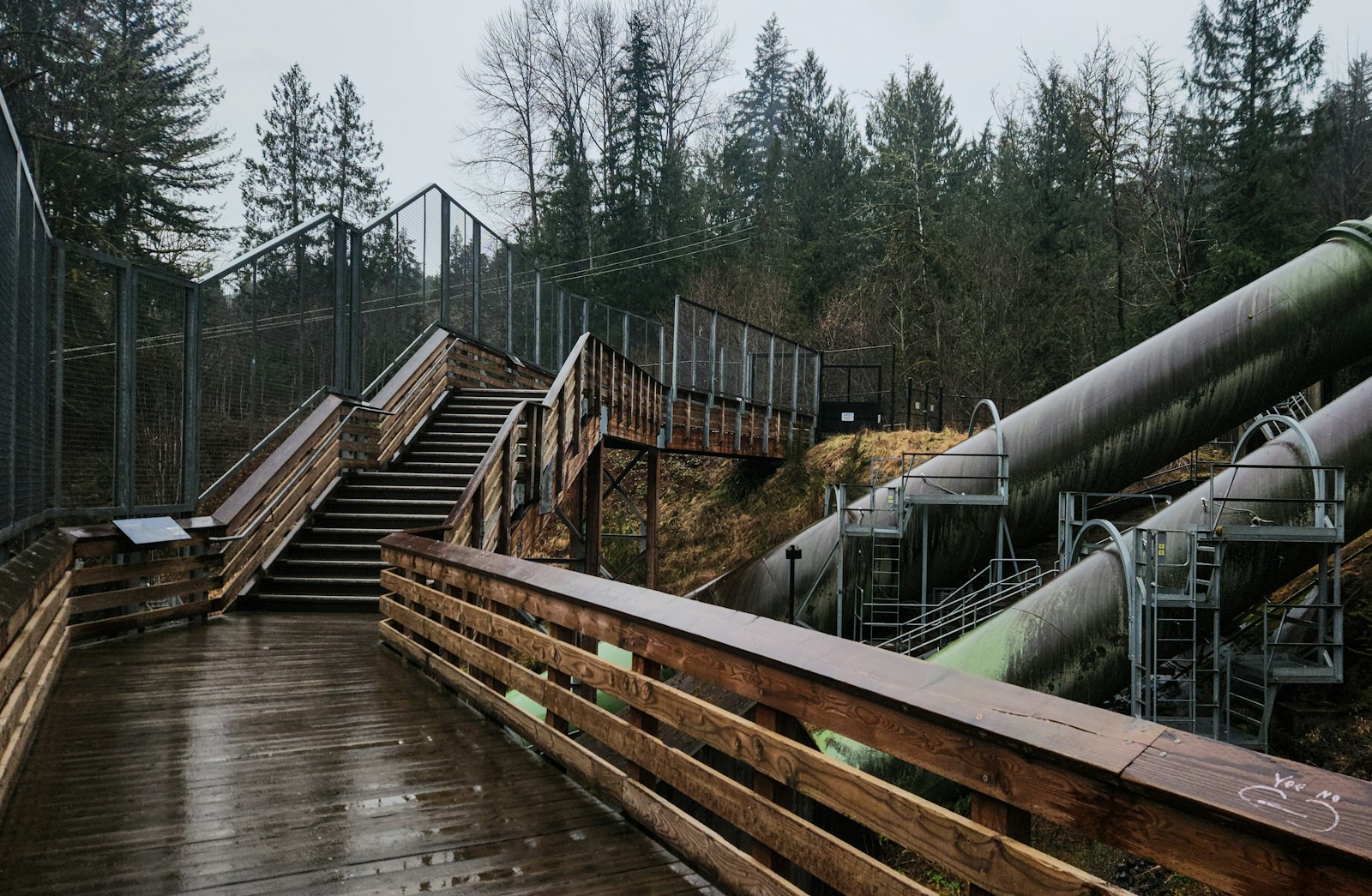
Featured photograph: Zoshua Colah via Unsplash, showing the Snoqualmie Falls hydroelectric facility and penstock infrastructure.