Neutral Grounding Resistor Sizing: Fault Current, Time Rating and Relay Checks
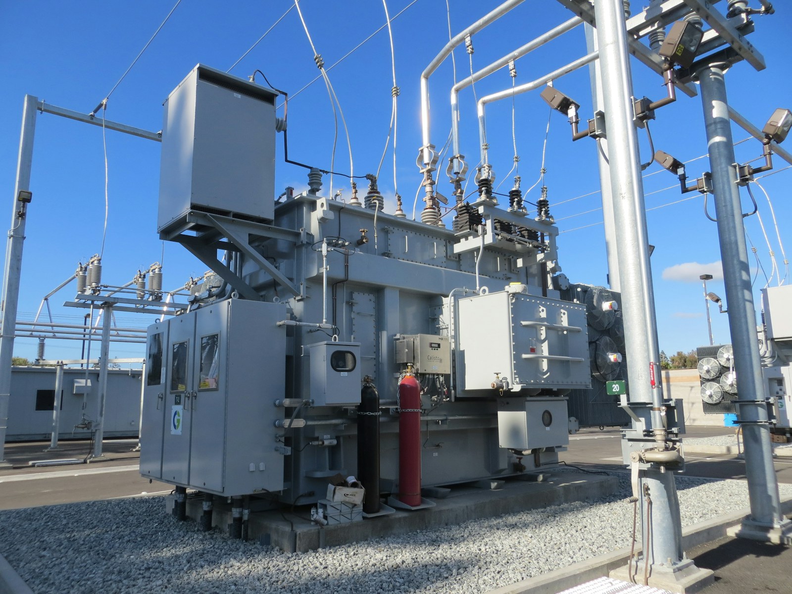
A neutral grounding resistor (NGR) limits single-line-to-ground current to a value that protection can detect and interrupt without exposing the transformer, generator, cables, and switchgear to the damage of a solidly grounded fault. Correct sizing is not simply “choose an ohmic value”: the engineer must coordinate system voltage, charging current, relay sensitivity, clearing time, thermal duty, insulation level, and resistor monitoring.
Quick sizing sequence
- Confirm the system line-to-line voltage and whether a real neutral is available.
- Select the grounding philosophy: high-resistance grounding (HRG), low-resistance grounding (LRG), or another method.
- Choose a target ground-fault current that exceeds charging current and gives dependable relay sensitivity.
- Calculate resistance from phase-to-neutral voltage: R = VLL /(√3 × Ig).
- Specify voltage, current, time, temperature-rise, enclosure, insulation, and environmental ratings.
- Prove the complete protection chain—CTs, relays, breaker time, backup protection, and NGR continuity monitoring.
What the NGR actually controls
For a bolted phase-to-ground fault close to the grounded source, the resistor is approximately exposed to the system phase-to-neutral voltage. Ignoring the comparatively small source and return-path impedances for a first estimate:
VLN = VLL/√3
RNGR = VLN/Ig
P = Ig2R = VLNIg
The selected current must be high enough to operate the protection but low enough to reduce point-of-fault energy. Eaton describes LRG systems as commonly limiting current to hundreds of amperes, while HRG normally limits it to 10 A or less. Those are application ranges, not universal settings; the network study decides the value.
Worked example: 13.8 kV system, 400 A for 10 seconds
Consider a 13.8 kV transformer with a grounded-wye secondary. The protection study requires 400 A maximum ground-fault current, and the source breaker will clear a bus fault in less than 0.8 s. A 10-second resistor duty is selected to provide margin and backup-clearing capability.
| Step | Calculation | Result |
|---|---|---|
| Neutral voltage | 13,800/√3 | 7,967 V |
| Resistance | 7,967/400 | 19.9 Ω |
| Instantaneous power | 400² × 19.9 | 3.18 MW |
| Energy at 10 s | 3.18 MW × 10 s | 31.8 MJ (8.84 kWh) |
The specification should therefore call for an NGR rated at the applicable voltage class, 400 A let-through current, approximately 19.9 Ω at its reference temperature, and a verified 10-second duty. Do not order a resistor from the arithmetic alone: resistance changes with temperature, tolerances matter, and the manufacturer must certify the thermal and dielectric design to the applicable standard.
Choosing HRG or LRG
| Question | HRG | LRG |
|---|---|---|
| Typical objective | Continue operating after the first ground fault while alarming and locating it | Trip the faulted circuit selectively with reduced damage |
| Fault-current scale | Usually a few amperes, commonly ≤10 A | Usually hundreds of amperes |
| Protection | Sensitive current/voltage detection, pulsing or fault-location scheme | Ground overcurrent protection with coordinated pickup and delay |
| Critical check | NGR current must dominate system charging current | Minimum fault current must remain above relay sensitivity |
Littelfuse guidance states that in alarm-only HRG or non-selective tripping applications, NGR let-through current should be greater than system charging current. For selectively coordinated tripping, its manual recommends definite-time ground-fault devices, pickup above the largest feeder charging current, and an NGR current roughly five to ten times that pickup. Measure or calculate charging current—do not guess from transformer MVA alone.
Time rating: coordinate it with the worst clearing path
An NGR marked “10 s” can carry its rated current for that stated short-time duty under specified conditions; it is not a continuous-duty device. The required duration must exceed the longest credible interval from fault inception to current interruption, including relay delay, breaker opening time, intentional coordination margin, and backup protection. IEEE C57.32 covers requirements, terminology, and test procedures for neutral grounding devices. Common duty classes include short-time ratings and continuous duty, but the project specification must use the current edition and manufacturer data.
- Primary clearing: relay pickup + intentional delay + breaker opening.
- Breaker failure: local failure timer + upstream breaker opening.
- Backup relay: longest permitted clearing time at rated NGR current.
- Repeated duty: cooling interval and permissible number of operations.
- Continuous service: harmonic neutral current and any allowed first-fault operation.
Relay checks for the 400 A example
Assume a neutral CT rated 400:5 and a source ground-overcurrent element. A 100 A primary pickup corresponds to 1.25 A secondary. If the largest healthy-feeder charging current is 20 A, pickup is five times that value and 25% of NGR current. A possible coordination ladder might be 0.20 s for the downstream feeder, 0.50 s for the incomer, and 0.80 s for source backup. These values are illustrative; the time-current study must include relay tolerances, CT error, breaker time, and minimum as well as maximum ground-fault current.
- Plot ground elements on the same time-current coordination sheet.
- Check sensitivity at the remote end of every protected feeder.
- Confirm CT knee point, burden, ratio, and transient performance.
- Test zero-sequence polarity and verify that normal load current does not flow through the residual measurement.
- Confirm the NGR monitor detects both an open resistor path and an unintended short circuit.
- Verify breaker-failure logic clears before the NGR short-time limit.
For a deeper protection workflow, see our relay coordination study guide and the practical article on CT saturation in protection systems.
NGR monitoring is part of the protection system
A ground-fault relay may appear healthy while an open NGR conductor, failed resistor element, loose terminal, or broken earth connection has removed the intended return path. Littelfuse notes that current-sensing ground-fault protection cannot operate as designed if the NGR or ground path is open. Continuous monitors typically supervise neutral voltage, current, and resistance/continuity. Their alarm and trip outputs should be included in SCADA, event recording, and the cause-and-effect matrix.
Specification checklist
- System voltage, frequency, source connection, and grounding point.
- Required let-through current and resistance tolerance at stated temperature.
- Short-time or continuous duty, maximum temperature rise, and cooling requirements.
- Insulation level, power-frequency withstand, and impulse withstand where applicable.
- Indoor/outdoor enclosure, IP/NEMA class, corrosion category, altitude, ambient temperature, seismic and vibration conditions.
- Neutral CT ratio/class, sensing resistor, monitor supply, communications, and alarm contacts.
- Grounding transformer rating if the system has no accessible neutral.
- Terminal arrangement, creepage/clearance, cable entry, lifting, guards, and anti-condensation heater.
- Routine and type-test certificates, resistance measurement, dielectric tests, and thermal-duty evidence.
Commissioning and maintenance tests
- Lock out, prove dead, discharge, and apply the site electrical-safety procedure.
- Inspect elements, insulators, enclosure bonding, terminals, earth conductor, contamination, and corrosion.
- Measure resistance using an appropriate low-resistance method and correct results to the manufacturer’s reference temperature.
- Inject the monitor inputs to prove open-circuit, short-circuit, alarm, and trip thresholds.
- Perform primary or secondary current injection through the protection chain and verify timestamps.
- Trip the intended breaker and prove backup operation, SCADA indication, event records, and interlocks.
- Record as-left settings and compare them with the approved coordination study.
Our low-resistance testing guide explains four-wire measurement principles that are useful during maintenance. Never perform a live ground-fault test unless it is part of an engineered, approved commissioning procedure.
Frequent design mistakes
- Using line-to-line voltage instead of line-to-neutral voltage in the resistance calculation.
- Selecting HRG current below the network’s capacitive charging current.
- Checking only the primary relay and ignoring breaker-failure clearing time.
- Specifying “400 A” without a time rating, voltage class, or resistance tolerance.
- Assuming an available transformer neutral is suitable without checking winding connection and zero-sequence path.
- Omitting NGR continuity monitoring.
- Applying a typical table without a project-specific short-circuit and coordination study.
Engineering references
- IEEE C57.32 scope: neutral grounding device requirements and tests.
- Eaton application paper on power-system neutral grounding techniques.
- Littelfuse SE-325 NGR monitor manual and selection guidance.
- Littelfuse illustrative NGR sizing chart.
Final design rule
Calculate the preliminary resistance from phase voltage and target current, then validate that choice against charging current, minimum relay pickup, maximum clearing time, thermal duty, CT performance, insulation, environment, and continuous monitoring. The resistor, relay, CT, breaker, and earth path form one protection system; approving them independently creates blind spots.
Featured photograph: American Public Power Association via Unsplash.