Electrical EngineeringElectrical Protection
CT Saturation in Protection Systems: Causes, Detection and Mitigation

Learn why protection CTs saturate and how burden, remanence and X/R ratio affect relays.
Protection principles
- Large current, DC offset, burden and remanence can saturate the core.
- Distortion may delay overcurrent or create false differential current.
- Check fault level, X/R ratio, CT ratio, leads and relay burden together.
- Mitigate with suitable CT class, lower burden and tested relay logic.
Study workflow
Start from the current single-line diagram, verified equipment data and maximum and minimum fault studies. Coordinate primary and backup protection while preserving sensitivity, selectivity, speed and security.
Commissioning checklist
Confirm CT and VT polarity, ratios and grounding; compare installed settings with the approved study; inject representative faults; verify trip matrices and event records; and document test equipment and tolerances.
Common mistake
Do not copy settings from another feeder. Network topology, fault level, breaker time, instrument transformers and equipment withstand are site-specific.
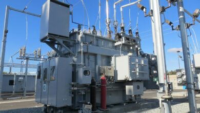
Featured photo by Anton Dmitriev on Unsplash.