Cable Derating at 50°C: Gulf Project Worked Example
A cable rated at 250 A in a reference table may not carry 250 A on a Gulf project. Ambient temperature, solar exposure, grouping, enclosure, soil and installation method all change heat dissipation. The correct workflow is to identify the reference rating, apply only the factors not already included, and then verify voltage drop, short-circuit withstand and protective-device coordination.
The core derating equation
If design current is Ib and the independent correction factors multiply to C, the minimum tabulated current rating is:
It,required ≥ Ib ÷ C
Alternatively, for a selected cable:
Iz,corrected = It × Ca × Cg × Ci × …
where the factors may represent ambient temperature, grouping, thermal insulation and other project conditions. Use factors from one compatible standard or manufacturer dataset. Never invent a factor or combine tables based on different reference conditions without reconciliation.
Worked 160 A example at 50°C
Assume a feeder has a design current of 160 A. The applicable table gives an ambient-temperature factor of 0.82 and a grouping factor of 0.80. No other correction factor applies.
| Item | Value | Calculation |
|---|---|---|
| Design current | 160 A | Load study |
| Temperature factor | 0.82 | Selected table at 50°C |
| Grouping factor | 0.80 | Actual loaded-circuit arrangement |
| Combined factor | 0.656 | 0.82 × 0.80 |
| Minimum tabulated rating | 244 A | 160 ÷ 0.656 |
Select a cable whose tabulated rating is at least 244 A for the stated reference installation. If the selected table rating is 260 A, its corrected capacity is 260 × 0.656 = 170.6 A, which exceeds 160 A. That result only passes the thermal-current test; the remaining checks can still require a larger cable.
What does 50°C ambient mean?
Define the temperature surrounding the cable, not the weather-app maximum. A cable inside a sun-exposed outdoor panel can experience air hotter than the shaded meteorological value. A cable tray near hot process equipment may have a persistent local temperature. Underground cable rating depends on soil temperature and thermal resistivity rather than outdoor air temperature.
Record whether 50°C is a design maximum, continuous ambient, short-duration extreme or enclosure internal temperature. Standards and manufacturer tables assume specific conditions; a factor is only meaningful when the project condition matches the table definition.
Installation method comes before correction factors
Choose the base rating for the real installation: cable in conduit, trunking, ventilated tray, free air, buried duct or direct burial. A factor cannot reliably convert an unrelated installation method. Also identify conductor material, insulation temperature class, number of loaded conductors, cable construction and single-core arrangement.
| Input | Why it changes rating |
|---|---|
| Copper or aluminium | Changes resistance, size and termination requirements |
| PVC, XLPE or other insulation | Sets permissible conductor temperature |
| Conduit, tray, duct or burial | Changes thermal path to the environment |
| Loaded conductors | Changes total heat generation |
| Trefoil or flat formation | Affects magnetic and sheath losses |
| Soil thermal resistivity | Can dominate buried-cable temperature |
Grouping factor: count thermally interacting circuits
Grouping factors depend on spacing, number of circuits, arrangement and whether adjacent circuits are loaded. Twelve cables on a wide ventilated ladder are not automatically equivalent to twelve tightly bundled cables in an enclosed trunking. Use the actual cross-section and routing details.
Parallel conductors require special care. Equal length does not guarantee equal current sharing if impedances, phase positions, terminations or conductor temperatures differ. Verify the permitted arrangement and ensure each parallel set has coordinated protection and installation.
Solar radiation is not ordinary ambient temperature
Direct sun adds heat beyond the surrounding air temperature. If the selected rating method assumes cables protected from solar radiation, an ambient-temperature factor alone does not cover exposed black cables or trays. Prefer shade, ventilated covers or a verified solar correction method. Do not install a cover that traps more heat than it blocks.
Buried cables need different inputs
For buried circuits, document soil temperature, thermal resistivity, burial depth, duct arrangement, spacing and drying risk. Desert soil may be dry and thermally resistive; imported backfill only helps when its installation and long-term moisture condition are controlled. A generic air-temperature derating factor is not a substitute for a buried-cable calculation.
IEC 60287 provides steady-state current-rating methods that account for cable losses and the thermal environment. Complex or high-value circuits deserve a project calculation using manufacturer construction data and surveyed route conditions.
Do not double-apply a correction factor
A common error is applying a 50°C factor to a manufacturer rating already calculated for 50°C, or applying grouping once in the software and again in a spreadsheet. Create an assumption register listing the reference condition of every table and the source of every factor.
| Factor | Reference condition | Project condition | Applied once? |
|---|---|---|---|
| Ambient temperature | As stated in rating table | 50°C cable environment | Confirm |
| Grouping | Single isolated circuit | Actual circuits and spacing | Confirm |
| Thermal insulation | No insulation contact | Survey route and penetrations | Confirm |
| Solar exposure | Protected from sun or stated basis | Outdoor route condition | Confirm |
Check the protective device after derating
For a conventional low-voltage feeder, the protective-device rating and cable capacity must satisfy the applicable coordination rules. Conceptually, design current should not exceed protective-device rating, and protective-device rating should not exceed the corrected cable capacity. Also verify the overload operating characteristic required by the selected code.
Ambient temperature can derate the breaker too. A breaker installed in a hot enclosure may carry less than its nominal rating or require a different setting. Coordinate cable and breaker using their actual environments rather than applying cable factors to the breaker.
Voltage-drop check
A cable that passes ampacity may fail voltage drop, especially on long Gulf infrastructure feeders. Calculate operating voltage drop at realistic power factor and conductor temperature. For motors, check starting voltage at the motor terminals and the upstream network response.
A simplified three-phase calculation uses line current, route length and the cable’s resistance and reactance. Use the project’s required formula and manufacturer data. Increasing conductor size can be justified by voltage performance even when the smaller cable is thermally acceptable.
Short-circuit withstand
Verify that the conductor and protective conductor can withstand the prospective fault current for the actual clearing time. The adiabatic relationship S ≥ I√t ÷ k is commonly used within its limits, where S is conductor area, I is fault current, t is clearing time and k depends on conductor and insulation materials.
Use the protection study’s fault current and clearing time, not a generic one-second value. Check screen, sheath, armour and bonding conductors where they carry fault current. Terminations and joints must also have adequate ratings.
Harmonics and neutral loading
Nonlinear loads can increase conductor heating. Triplen harmonics add in the neutral of a three-phase four-wire system, so the neutral may not be lightly loaded even when phase currents appear balanced. IEC 60364-5-52 includes cable-sizing considerations for harmonic currents. Obtain measured or modeled harmonic spectra for data centers, LED loads, UPS systems and variable-speed drives.
Motor feeders need two operating points
Check continuous current at the worst ambient and starting performance at the weakest supply condition. The cable must coordinate with overload and short-circuit protection without nuisance tripping during an acceptable start. Long acceleration, frequent starts and high enclosure temperature can change the thermal duty.
Field verification after energization
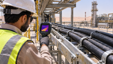
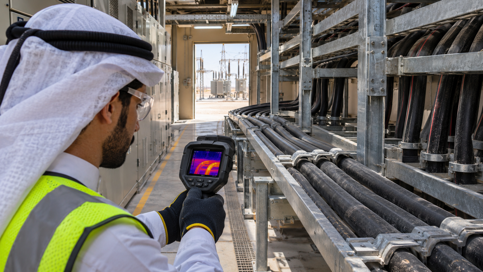
Commissioning measurements do not replace design, but they can reveal wrong assumptions. Record phase and neutral current, load balance, enclosure temperature and thermal images at stable representative load. Investigate hot joints, unequal parallel-cable sharing or local heating rather than simply raising a breaker setting.
Design checklist
- Confirm design current and duty cycle.
- Select the correct base installation method.
- Record conductor, insulation and loaded-conductor count.
- Define cable-environment temperature, not only weather temperature.
- Apply grouping, solar, insulation and soil factors only where relevant.
- Prevent double derating by documenting table reference conditions.
- Verify corrected ampacity and breaker coordination.
- Check operating and motor-start voltage drop.
- Verify conductor, screen and protective-conductor fault withstand.
- Assess harmonics, neutral current and parallel sharing.
- Validate accessible connections thermographically after loading.
Technical references
Use the current project-adopted edition of IEC 60364-5-52 for wiring-system selection and erection, and the applicable IEC 60287 cable-rating methods for engineered calculations. Manufacturer data and local authority requirements remain essential. Original educational content by ST College.