Parallel Transformers: Conditions, Load Sharing and a Worked kVA Example

Operating transformers in parallel can improve reliability, add capacity in stages and simplify maintenance—but only when their voltage ratios, vector groups, impedances and tap positions are compatible. Two transformers can have the same kVA rating and secondary voltage yet still circulate current or share load badly.
Why operate transformers in parallel?
- Maintain supply while one unit is isolated for planned work.
- Add capacity as demand grows without replacing the first transformer.
- Run one unit during light load to reduce no-load losses.
- Use standard transformer sizes and keep a common spare strategy.
- Improve operational flexibility during feeder or busbar maintenance.
These benefits depend on a protection and switching scheme designed for the increased fault level and possible reverse or circulating currents.
Mandatory compatibility checks
| Parameter | Why it matters |
|---|---|
| Voltage ratio | A ratio mismatch creates circulating current even with little external load. |
| Polarity | Incorrect polarity can produce a near short circuit when secondaries are connected. |
| Phase sequence | All three phases must appear in the same order. |
| Vector group | Phase displacement between HV and LV must be compatible. |
| Tap position | Different taps create unequal secondary no-load voltages. |
| Percentage impedance | Determines how the total kVA divides between transformers. |
| X/R ratio | Different impedance angles cause unequal kW and kvar sharing. |
| Frequency | Both units must be designed for the system frequency. |
Vector group: the first go/no-go check
The vector-group clock number describes the phase displacement between high- and low-voltage windings. Transformers with identical groups—such as Dyn11 and Dyn11—are normally straightforward candidates, subject to the other checks. Different clock numbers may place their secondary phase voltages tens or hundreds of electrical degrees apart; closing them onto the same bus can be destructive.
Some different groups can theoretically be made compatible by external phase reconnection, but this must be designed and verified by a qualified engineer. A nameplate similarity is not enough: confirm terminal markings, drawings and measured phase relationship.
How percentage impedance controls kVA sharing
For transformers with equal secondary no-load voltage and similar impedance angle, load divides approximately in inverse proportion to their per-unit impedances on a common base. A practical formula is:
S₁ / S₂ ≈ (Srated1 / Z%₁) / (Srated2 / Z%₂)
Another useful method is to calculate each transformer’s capacity-to-impedance factor:
Kᵢ = Srated,i / Z%ᵢ
Then its share of total load is:
Sᵢ = Stotal × Kᵢ / ΣK
Worked example: unequal ratings and impedances
Two 11/0.415 kV transformers operate in parallel:
- Transformer A: 1000 kVA, impedance 6%.
- Transformer B: 1500 kVA, impedance 7%.
- Total bus load: 2200 kVA.
Calculate the sharing factors:
- KA = 1000 / 6 = 166.7
- KB = 1500 / 7 = 214.3
- ΣK = 381.0
Approximate load shares:
- SA = 2200 × 166.7 / 381.0 ≈ 962 kVA
- SB = 2200 × 214.3 / 381.0 ≈ 1238 kVA
Transformer A is at 96.2% loading, while Transformer B is at only 82.5%. The pair has 2500 kVA of nameplate capacity, but the smaller unit reaches its limit first.
Maximum usable combined load
To prevent Transformer A from exceeding 1000 kVA, solve using its calculated fraction:
Stotal,max = 1000 / (166.7 / 381.0) ≈ 2286 kVA
At that point Transformer B carries about 1286 kVA. Therefore the practical parallel capacity is approximately 2286 kVA, not the arithmetic sum of 2500 kVA.
Why equal impedance percentage is not the whole story
Two transformers may have the same Z% but different resistance-to-reactance proportions. One unit can then carry more real power while the other carries more reactive power. The total kVA meters might look acceptable while one winding operates at a worse power factor or higher current. For unlike designs, compare the resistance and reactance components or the X/R ratio—not only the magnitude printed on the nameplate.
Circulating current from voltage mismatch
If the no-load secondary voltages differ, a current circulates between transformers even when the external load is small. An approximate per-unit expression is:
Icirc,pu ≈ ΔVpu / (Z1,pu + Z2,pu)
If two equal 6% impedance transformers differ in secondary voltage by 1%, the approximate circulating current is 0.01 / (0.06 + 0.06) = 0.083 pu, or about 8.3% of rated current. This current consumes thermal capacity but does not serve the external load.
Tap changer considerations
Fixed off-circuit taps must normally be placed on matching positions before paralleling. With on-load tap changers, independent voltage controllers can “fight” each other: one raises its tap while the other lowers, increasing circulating reactive current. Parallel control schemes use master-follower logic, circulating-current compensation or reactive-current balancing to coordinate tap movement.
Fault-level impact
Paralleling transformers reduces source impedance seen from the LV bus and increases prospective short-circuit current. Before closing the bus coupler, verify:
- Switchboard short-circuit withstand and making capacity.
- Breaker interrupting ratings.
- Busbar thermal and electrodynamic withstand.
- Protection settings and discrimination.
- Arc-flash study assumptions and labels.
- Earthing conductor duty and neutral fault current.
A system that is safe in split-bus operation may exceed equipment ratings when both transformers feed the same bus.
Protection issues in parallel operation
- Transformer differential protection: CT ratios and vector compensation must match each unit.
- Restricted earth fault: confirm the protected zone and neutral arrangement.
- Overcurrent coordination: account for fault contribution from both transformers.
- Reverse power or directional elements: may be useful in complex networks.
- Busbar protection: update zones and isolator replica logic for the coupler state.
- Inrush: sympathetic inrush can affect an energised transformer when another is switched on.
Neutral and earthing checks
When both LV neutrals are connected, zero-sequence current paths can change. Confirm winding connections, neutral-earthing resistors or solid earthing points, and whether parallel neutral paths create unwanted circulating current. Avoid creating multiple uncontrolled neutral-to-earth bonds in low-voltage systems.
Commissioning sequence before first parallel close
- Compare nameplates, vector groups, ratings, impedances and tap positions.
- Verify protection drawings, CT circuits and interlocking.
- Perform insulation, ratio, winding-resistance and polarity tests as required.
- Confirm phase sequence on both sources.
- With the bus coupler open, measure phase-to-phase voltage across corresponding terminals.
- Check the voltage difference is within the approved limit on every phase.
- Close under controlled conditions with low load where the operating procedure allows.
- Measure each transformer’s phase current, kW, kvar and power factor.
- Increase load in steps and confirm sharing against the study.
- Record thermal images and baseline operating data.
Operational warning signs
- High current on one transformer at low total bus load.
- Reactive power flowing in opposite directions between units.
- Tap changers moving frequently or in opposite directions.
- Unequal phase currents not explained by the downstream load.
- Unexpected neutral current.
- One transformer reaching temperature alarm before the other.
- Protection pickup or nuisance trips after closing the bus coupler.
When not to parallel
Keep the transformers separated until an engineering study resolves any incompatible vector group, unacceptable ratio mismatch, excessive impedance difference, insufficient switchboard fault rating, uncontrolled neutral path or inadequate protection. Operational pressure is not a reason to bypass a failed compatibility check.
Frequently asked questions
Can transformers with different kVA ratings operate in parallel?
Yes, if voltage ratio, vector group and other requirements are compatible. Load sharing depends on rating and impedance, so the usable combined capacity may be less than the sum of nameplates.
How close should percentage impedances be?
Project standards and manufacturer guidance should define the tolerance. The engineering check must calculate actual sharing at maximum load rather than rely on a single generic percentage rule.
Can Dyn11 and Dyn1 transformers be paralleled directly?
Normally no: their clock numbers indicate different phase displacement. Any proposed reconnection requires a formal design, terminal verification and commissioning tests.
Why does one transformer carry more kvar?
Different impedance angles, voltage ratios or tap positions can cause unequal reactive-power sharing even when total kVA appears reasonable.
Conclusion
Successful parallel operation requires more than matching voltage and kVA. Verify vector group, polarity, phase sequence, ratio, taps, impedance magnitude and X/R ratio; then recalculate load sharing and fault level. A controlled commissioning test should prove the study before the system is released for normal operation.
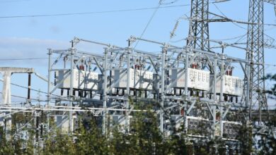
Featured photo: Zoshua Colah via Unsplash. This article is educational; site-specific switching and protection decisions require approved studies and procedures.