IEC 61439 Forms of Separation: How to Choose Form 1, 2, 3 or 4
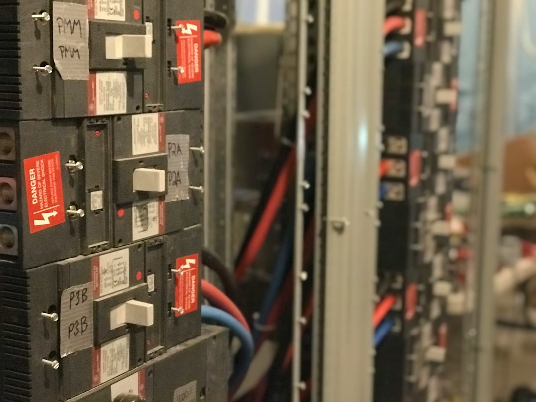
Photo by Troy Bridges via Unsplash, used under the Unsplash License.
Quick answer: Forms 1, 2, 3 and 4 describe how an IEC 61439-2 low-voltage power switchgear assembly separates busbars, functional units and external-conductor terminals. A higher form can support specific maintenance or cable-work tasks while adjacent parts remain energised, but it does not automatically make the assembly safer, arc-resistant or suitable for live work. Select the form from the operating task, competence, outage strategy and verified assembly design.
What internal separation is designed to achieve
Internal separation uses partitions, barriers, insulation or device housings to divide parts of a power switchgear and controlgear assembly. The practical objectives can include limiting accidental contact with adjacent live parts, reducing the chance that a tool or loose component reaches another compartment, and allowing defined inspection or maintenance tasks without isolating the whole assembly.
Separation is only one layer of risk control. The switching procedure, isolation points, interlocks, protective devices, enclosure integrity, labels and worker competence remain essential. The project specification should describe the task the separation must enable rather than naming a form with no operating context.
Form 1: no internal separation
Form 1 provides no internal separation between busbars and functional units. It may be appropriate where the complete assembly can be isolated for internal work, continuity requirements are modest and the risk assessment supports that approach. It can be compact and economical, but internal access normally exposes the worker to several parts of the assembly at the same time.
Form 2: busbars separated from functional units
Form 2 separates the busbars from the functional units. The subcategories distinguish whether terminals for external conductors are separated from the busbars. This arrangement can reduce exposure to the main busbar system during some work on a functional unit, but it does not separate each functional unit from its neighbours.
Ask where cable terminals are located, what remains live when a feeder is switched off, and how a technician reaches settings, auxiliary terminals and cable lugs. A label stating “Form 2” is not enough to answer those questions.
Form 3: functional units separated from each other
Form 3 adds separation between functional units while their external-conductor terminals are not separated from the terminals of other functional units. It can support limited work on one unit while adjacent units remain in service, subject to the manufacturer’s instructions and the site’s safe system of work.
This form is often considered for industrial distribution where a complete shutdown is costly but cable termination work is not expected while adjacent circuits remain energised. The actual access path and terminal arrangement still need drawing-level review.
Form 4: terminals associated with each functional unit are separated
Form 4 separates functional units from one another and separates the external-conductor terminals associated with one functional unit from those of other units. The subcategory distinguishes the relationship between those terminals and their own functional unit. This can provide the most extensive separation of the four basic forms.
Form 4 is not permission for live work. It must be combined with the task-specific isolation procedure, verification of dead, arc-flash risk assessment, local law and competent-person controls. It also increases enclosure volume, interfaces and cost, so it should be specified for a demonstrated operational need.
Comparison table
| Form | Main separation | Typical operational question |
|---|---|---|
| 1 | No internal separation | Can the whole assembly be isolated for every internal task? |
| 2 | Busbars separated from functional units | Does the team need access to a unit with the busbar compartment protected? |
| 3 | Busbars separated and functional units separated from each other | Must one unit be inspected while adjacent units remain in service? |
| 4 | Form 3 plus separation of terminals by associated functional unit | Is defined cable-side work required without shutting unrelated feeders? |
A worked selection example
Consider a hospital main low-voltage board with two incomers, a bus coupler and outgoing feeders. The facilities team requires relay inspection on one outgoing feeder without interrupting unrelated essential services. Cable replacement is always performed during a planned shutdown, and the site’s rules prohibit live cable work.
- Form 1 does not match the requirement because adjacent internal parts would not be separated.
- Form 2 separates the busbars but does not separate neighbouring functional units.
- Form 3 may match the stated relay-inspection task if access, auxiliary circuits and remaining live parts are protected as required.
- Form 4 may add cost and space without a corresponding benefit if cable terminals are never accessed under the proposed operating state.
The provisional choice is therefore Form 3, subject to the assembly manufacturer’s verified design, detailed access review and the hospital’s risk assessment. If the owner later requires cable-side maintenance while adjacent feeders remain energised, the selection basis must be reconsidered.
Do not confuse separation with internal arc protection
Partitions may influence how an internal fault develops, but the form of separation is not an internal-arc classification. IEC TS 61641:2026 addresses verification methods intended to limit personnel injury, damage and loss of availability from internal arc faults in low-voltage assemblies. If internal-arc mitigation is required, state that requirement separately and define the operating conditions, protection clearing time and installation arrangement.
Temperature rise and ventilation
Additional partitions can restrict airflow and create hot spots. The assembly must retain its verified current ratings and temperature-rise performance in the supplied configuration. Do not add site-made barriers, cable bundles or blanking plates without checking the original manufacturer’s instructions.
High ambient temperature in Gulf plant rooms deserves particular attention. Equipment ratings, diversity, enclosure ventilation and active-cooling dependencies must be evaluated at the project design temperature—not assumed from a 35°C reference condition.
Protection against remaining live parts
IEC 61439-2:2020 clarifies that, for forms higher than Form 1, parts inside a functional-unit compartment that remain live after that unit is switched off are protected to at least IPXXB. The design review should identify such parts on drawings and during inspection. Control power, metering circuits and backfeeds are common sources of unexpected voltage.
Information the specifier should provide
- System voltage, frequency, fault level and earthing arrangement.
- Rated and design currents, diversity and future expansion.
- Indoor or outdoor service conditions and maximum ambient temperature.
- Tasks expected while part of the assembly remains energised.
- Access direction, cable entry, gland location and termination size.
- Required outages, redundancy and restoration sequence.
- Competence and tools of the people performing each task.
- Any internal-arc, arc-detection or pressure-relief requirement.
- Verification documents, routine-verification records and as-built drawings.
Factory and site inspection checklist
- Confirm the declared form and subcategory on approved drawings.
- Trace busbars, functional units and external-conductor terminals physically.
- Check that partitions match the verified assembly design.
- Identify all parts that remain live when a functional unit is off.
- Verify shutters, interlocks, doors, covers and tool requirements.
- Check cable bending space and safe termination access.
- Review temperature-rise evidence for the actual arrangement.
- Confirm labels, circuit references and backfeed warnings.
- Record routine-verification results and approved deviations.
- Update the operating procedure after commissioning.
Common specification mistakes
- Writing “Form 4” without identifying the task it must support.
- Assuming a higher form creates arc-resistant switchgear.
- Ignoring cable-gland and terminal location.
- Adding barriers after manufacture without verification.
- Failing to include control and auxiliary supplies in the isolation plan.
- Choosing the smallest enclosure without checking temperature rise.
- Treating separation as permission for live work.
Frequently asked questions
Is Form 4 always safer than Form 3?
No. The appropriate form depends on the task, access, isolation philosophy and verified design. An unnecessarily complex arrangement can add cost and thermal constraints without reducing the actual operational risk.
Does Form 4 mean arc-resistant?
No. Forms of separation and internal-arc performance are different requirements. Specify and verify internal-arc mitigation separately when the risk assessment requires it.
Can site personnel modify partitions?
Only through an approved change process involving the assembly manufacturer or responsible engineering authority. A modification can affect clearances, IP protection, temperature rise and the verified design.
Related guides
- Low-voltage switchboard design and IEC 61439 verification
- Relay coordination study workflow
- LSIG trip-unit settings guide
Authoritative references
- IEC 61439-2:2020 — power switchgear and controlgear assemblies
- IEC TR 61439-0:2022 — guidance for specifying assemblies
- BEAMA Guide to Forms of Separation
This educational guide does not replace the project specification, risk assessment, applicable national rules or the complete standards. Final selection and work procedures require qualified engineering and safety review.