Earthing Grid Design for Small Substations: A Practical Workflow
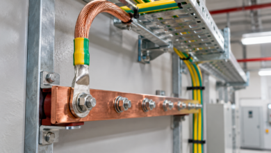
Substation earthing is designed to control touch and step voltage during faults, not merely to obtain a low resistance reading. Soil, fault current split, clearing time and surface treatment all matter.
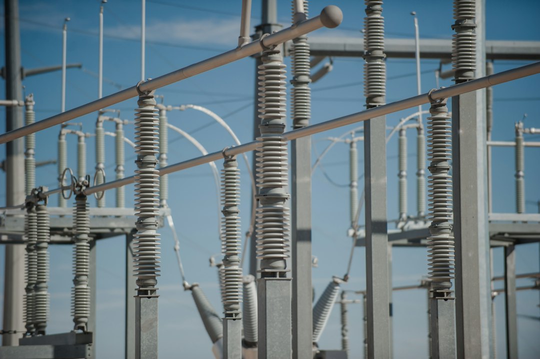
Photo by American Public Power Association on Unsplash.
Why this topic matters
Good engineering decisions connect calculations with site conditions, equipment data and operating scenarios. The workflow below is intended for preliminary design, technical review and commissioning preparation. It does not replace the current local code, utility rules or a competent professional’s approval.
Core engineering checks
- Obtain representative soil-resistivity measurements across seasons and depths.
- Estimate the portion of earth-fault current that actually enters the grid.
- Lay out buried conductors and rods around equipment, fences and operating positions.
- Evaluate touch, step and transferred potentials, then verify continuity after construction.
Calculation starting point
A resistance target alone is insufficient. The safety assessment compares calculated grid potential rise and local surface gradients with tolerable limits for the assumed body and fault duration.
Recommended workflow
- Collect evidence: obtain drawings, interval data, nameplates, manufacturer curves and site measurements.
- Define scenarios: include normal operation, peak demand, maintenance states, credible faults and future expansion.
- Calculate: state assumptions, units, correction factors and the source of every input.
- Coordinate: check interfaces with protection, controls, communications, civil works and operations.
- Verify: turn each design assumption into an inspection, measurement or functional test.
Europe and Gulf considerations
Dry, high-resistivity Gulf soil can require deeper electrodes, soil improvement or expanded grids. Wet European sites may have lower resistance but still present transferred-potential and corrosion concerns.
Common mistakes
- Using nominal ratings without environmental or installation derating.
- Checking only one operating condition.
- Relying on software output without validating inputs and boundary conditions.
- Leaving commissioning criteria undefined until the equipment arrives.
- Failing to record the final settings, firmware, drawings and test results.
Handover checklist
Keep the approved design basis, calculations, single-line or network diagram, equipment schedules, protection and control settings, inspection records, test certificates, operating instructions, maintenance intervals and an as-built change log. A useful handover package allows a future engineer to understand not only what was installed, but why.
Frequently asked questions
Can this method be used for final design?
It is a strong review framework, but final values must come from project-specific data and the current requirements of the responsible authority.
What should be verified first?
Verify the input data that most strongly changes safety or capacity: source strength, load profile, environment, installation method and protective-device characteristics.
How should uncertainty be handled?
Use conservative but explicit assumptions, test sensitivity to uncertain inputs, and replace assumptions with measurements during commissioning.
Explore more practical guides in our engineering library and English Engineering section.