Transformer Inrush Current: Causes, Estimation and Protection Settings
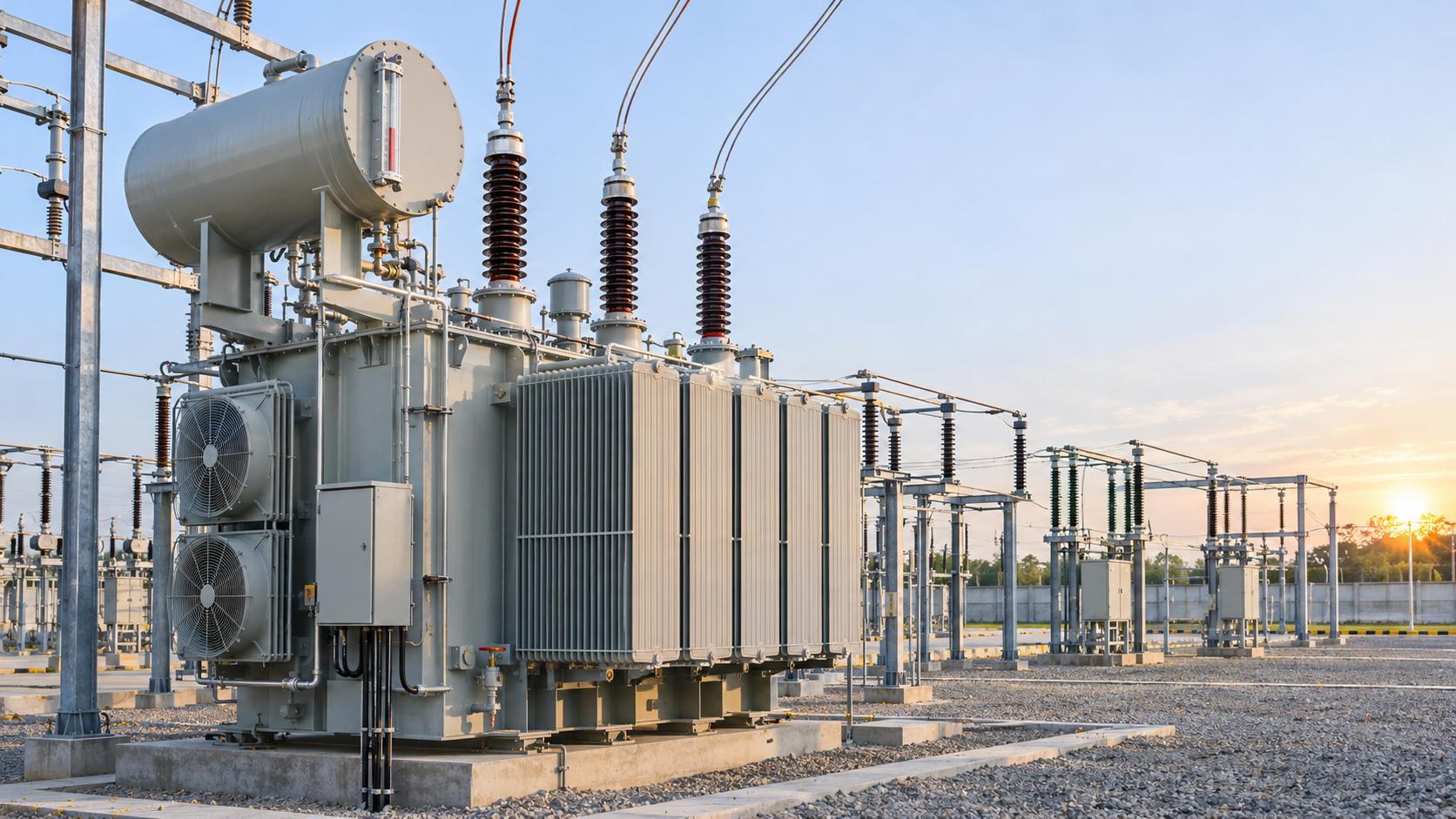
Quick answer: transformer inrush current is a short, high magnetizing current that appears when a transformer is energized. Its first peak can be many times rated current because residual core flux and the switching instant may drive the core into saturation. It is normal operating current, but protection must distinguish it from an internal fault.
Why transformer inrush current occurs
A transformer core needs alternating flux to reproduce the applied sinusoidal voltage. If the breaker closes at an unfavorable point on the voltage wave, the new flux can add to residual magnetism left in the core. The resulting asymmetrical flux may exceed the normal operating range and push the core into saturation. Magnetizing inductance then falls sharply and the supply delivers a large, distorted current.
The peak is influenced by the closing angle, residual flux magnitude and polarity, core construction, transformer rating, energizing side, source impedance and whether a load is already connected. For this reason, a precise value normally requires manufacturer data or an electromagnetic transient study.
How large can the inrush be?
Engineering guides commonly show first peaks in the approximate range of 8–15 times rated current for many power and distribution transformers. Smaller units or unfavorable switching conditions can produce still higher peaks. These values are screening ranges—not guaranteed design data.
For a three-phase 1,000 kVA, 11 kV transformer, the rated HV current is:
In = 1,000,000 / (√3 × 11,000) = 52.5 A
An initial screening range of 8–12 × In would therefore be about 420–630 A on the HV side. Do not use this range as a relay setting by itself; compare the manufacturer’s inrush envelope with the complete protection time-current curve.
Inrush current versus internal fault
| Characteristic | Energization inrush | Internal transformer fault |
|---|---|---|
| Duration | Decays after energization | Persists until isolated |
| Waveform | Strongly asymmetrical and distorted | Depends on fault type and source |
| Second harmonic | Often significant | Normally much lower |
| System event | Breaker closing or voltage restoration | Insulation or winding failure |
| Protection response | Restrain differential trip when criteria are met | Fast selective isolation |
Protection checks that prevent nuisance trips
- Obtain the inrush envelope. Use manufacturer curves whenever available, particularly for large units, low-loss cores or energization from the LV side.
- Plot the breaker or fuse curve. The protective device must ride through normal energization while still protecting conductors and transformer thermal limits.
- Apply differential inrush restraint. Modern 87T relays use harmonic and waveform criteria rather than assuming every differential current is a fault.
- Coordinate overcurrent stages. Instantaneous pickup must not operate for expected inrush, while delayed stages remain coordinated with downstream protection.
- Study sympathetic inrush. Energizing one transformer can disturb an already energized parallel transformer, especially on a weak source.
Practical mitigation options
Where inrush causes unacceptable voltage dips or protection constraints, engineers may use sequential energization, controlled point-on-wave switching, pre-insertion impedance, staged load connection or a stronger source. The appropriate solution depends on transformer size, network short-circuit level, switching frequency and the sensitivity of nearby loads.
Transformer Inrush FAQ
Is inrush current a short circuit?
No. It is a magnetizing transient associated with core saturation. It can resemble a fault to protection that considers only current magnitude.
Why is the second harmonic important?
Inrush waveforms often contain substantial second harmonic content. Transformer differential relays can use this feature as one criterion to restrain operation during energization.
Can inrush be calculated exactly from transformer kVA?
No. kVA provides rated current, but an accurate transient estimate also needs core, residual-flux, switching-angle and network data. Use manufacturer information for final protection studies.
Related guides: transformer winding resistance measurement and LV and MV fuse protection.