Detuned Capacitor Bank Design: Harmonic Resonance, 7% Reactors and a Worked Example
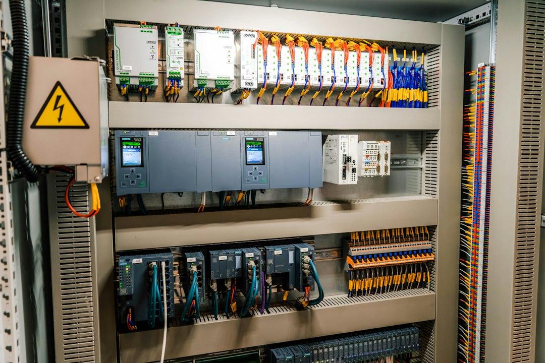
Power-factor-correction capacitors can interact with the upstream transformer and network inductance to create parallel resonance. In a plant with variable-frequency drives, UPS systems, rectifiers or welders, the result may be capacitor overheating, blown fuses, distorted bus voltage and repeated contactor failure. A detuned capacitor bank adds a series reactor to shift the resonance below the dominant harmonic.
How resonance appears in a power system
The utility source and transformer are mainly inductive, while the correction bank is capacitive. At one frequency their reactances can cancel. The resulting parallel resonance presents a high impedance to harmonic current, magnifying harmonic voltage and driving excessive current through the capacitor branch.
The approximate parallel-resonance harmonic order for a simple system is often estimated from:
hr ≈ √(Ssc / Qc)
where Ssc is the short-circuit power at the bus and Qc is the connected capacitor kvar. This is a screening calculation; cable, motor, generator and multiple-bank effects require a network model.
Worked resonance screening example
A 400 V bus has an estimated short-circuit power of 20 MVA and a 400 kvar capacitor bank:
hr ≈ √(20,000 / 400) = √50 = 7.07
The natural resonance is near the seventh harmonic. If the plant has significant seventh-harmonic current, a plain capacitor bank could amplify distortion. Changes in utility configuration or the number of connected capacitor steps move the resonance, so every operating combination matters.
What the detuning percentage means
The detuning factor is commonly expressed at the fundamental frequency as:
p = XL / XC
For a 7% reactor, p = 0.07. The series-resonant frequency is approximately:
fr = f1 / √p
On a 50 Hz system:
fr = 50 / √0.07 ≈ 189 Hz
This is below the fifth harmonic at 250 Hz, which helps prevent the capacitor branch from attracting fifth-harmonic current as a tuned filter would.
Common detuning choices
| Reactor factor | Series-resonant frequency at 50 Hz | Typical intent |
|---|---|---|
| 5.67% | ≈210 Hz | Below fifth harmonic, with a different impedance characteristic |
| 7% | ≈189 Hz | Widely used below the fifth harmonic |
| 14% | ≈134 Hz | Below the third harmonic for special network conditions |
The correct factor depends on the measured spectrum, system frequency, utility requirements, capacitor design and possible audio-frequency control signals. Do not select 7% only because it is common.
Capacitor voltage rises with a series reactor
At the fundamental frequency, the reactor and capacitor voltages oppose each other. The capacitor therefore sees a voltage higher than the bus. An approximate multiplier is:
VC ≈ Vbus / (1 − p)
For a 7% reactor on a 400 V system:
VC ≈ 400 / 0.93 ≈ 430 V
That is before allowing for utility overvoltage, harmonic voltage and tolerance. It explains why detuned banks often use capacitors rated above the nominal system voltage. The manufacturer must coordinate capacitor voltage, kvar and reactor current as one assembly.
Do not compare capacitor kvar labels directly
A capacitor’s kvar depends on applied voltage and frequency:
Q ∝ V²
A capacitor marked 25 kvar at 440 V will deliver only about:
25 × (400 / 440)² ≈ 20.7 kvar
before considering the reactor. A bank designer must calculate the final net kvar at the actual bus voltage with the selected reactor, rather than add nameplate kvar blindly.
Step-by-step design workflow
- Collect load data: maximum and minimum kW, present power factor and target power factor.
- Measure harmonics: record voltage and current spectra over representative production cycles.
- Model network strength: include transformer impedance, utility fault level, generators and bus ties.
- List nonlinear loads: VFD pulse numbers, UPS, rectifiers, welders and LED power supplies.
- Screen resonance: calculate possible resonant orders for each capacitor-step combination.
- Select detuning: place series resonance away from significant harmonics and control frequencies.
- Rate components: capacitor voltage, reactor current and temperature class, contactors, fuses and busbars.
- Verify distortion: run a frequency scan and harmonic load-flow study for critical systems.
- Commission: measure current, temperature, kvar and THD with steps switching.
Power-factor kvar calculation
The basic correction requirement remains:
Qc = P × (tan φ₁ − tan φ₂)
Suppose a plant operates at 800 kW and 0.78 power factor, with a target of 0.95:
- tan(cos⁻¹ 0.78) ≈ 0.802
- tan(cos⁻¹ 0.95) ≈ 0.329
- Qc ≈ 800 × (0.802 − 0.329) ≈ 378 kvar
A practical bank might use approximately 400 kvar in several steps, but the final net output, step sizes and detuning must be recalculated using the actual component ratings.
How to choose step sizes
Unequal binary-style steps such as 25, 25, 50, 100 and 200 kvar allow fine control over a wide range. Equal steps simplify spares. The best arrangement depends on how quickly the load changes and the smallest meaningful correction increment. Avoid rapid hunting around the controller’s switching thresholds.
Switching devices and inrush
Capacitor energisation produces high transient current, especially when another charged step is already connected. Use capacitor-duty contactors with pre-insertion resistors or dedicated switching devices. Check:
- Peak inrush withstand.
- Making duty with back-to-back capacitor steps.
- Discharge time before reconnection.
- Contactor and fuse ratings with reactor current.
- Switching rate and controller delay.
Reactor thermal design
The reactor carries fundamental capacitor current plus harmonic current. Specify current tolerance, linearity, temperature class and thermal switch. Poor ventilation can cause insulation ageing even when RMS current appears acceptable. Temperature sensors should alarm or trip before permanent damage.
Protection and monitoring
| Function | Purpose |
|---|---|
| HRC fuses or breaker | Clear capacitor or branch faults |
| Unbalance protection | Detect failed elements in larger banks |
| Thermal switches | Protect detuning reactors from overheating |
| Overvoltage supervision | Prevent operation during sustained high voltage |
| Harmonic or THD alarm | Identify changing plant conditions |
| Step-current monitoring | Detect lost capacitance or fuse operation |
Detuned bank versus tuned filter
A detuned bank places its series resonance below a dominant harmonic and is mainly intended for safe reactive-power correction. A tuned filter is intentionally tuned close to a selected harmonic to absorb it. Tuned filters need more detailed studies because they can attract harmonic current from the wider network and interact with other filters.
When an active harmonic filter may be better
An active filter can inject compensating current over a range of harmonics and may also provide reactive current. It is useful when the load spectrum changes significantly, when space is limited, or when a passive solution would require several tuned branches. However, it has semiconductor losses, current limits and control requirements. Hybrid solutions combine detuned capacitors for bulk kvar with an active filter for residual harmonics.
Commissioning measurements
- Bus voltage and frequency before and after energisation.
- Current in every capacitor step and phase.
- Net kvar and achieved power factor.
- Voltage THD and individual harmonic components.
- Reactor and capacitor-case temperatures after thermal stabilisation.
- Step-switching transient and contactor operation.
- Controller CT polarity and location.
Troubleshooting symptoms
| Symptom | Possible cause |
|---|---|
| Repeated fuse operation | Harmonic overcurrent, inrush, failed capacitor or wrong fuse class |
| Hot reactor | Unexpected spectrum, blocked ventilation, saturation or undersizing |
| Capacitor bulging | Overvoltage, overheating, excessive harmonic current or ageing |
| Power factor hunting | Step too large, short delay, unstable load or CT error |
| THD increases when bank connects | Network resonance or unsuitable detuning |
Common mistakes
- Installing a plain capacitor bank on a VFD-heavy bus without measurements.
- Selecting reactor percentage without checking the harmonic spectrum.
- Using 400 V capacitors on a 400 V bus with a 7% reactor.
- Ignoring generator operation, which changes system impedance dramatically.
- Assuming a detuned bank will guarantee compliance with harmonic limits.
- Failing to model partial-step operation.
Frequently asked questions
Does a 7% reactor remove the fifth harmonic?
No. It shifts the branch resonance below the fifth harmonic and limits harmonic amplification. Some harmonic current may flow, but the bank is not necessarily designed as a fifth-harmonic filter.
Can a detuned bank work with a standby generator?
Possibly, but the generator has a much lower short-circuit strength than the utility and may create new resonance or voltage-control problems. Study the generator mode separately and interlock capacitor steps if required.
Why are capacitor cans rated 440 V on a 400 V system?
The series reactor raises capacitor terminal voltage, and additional margin is needed for supply variation and harmonics. The final rating must be calculated for the whole assembly.
Conclusion
A reliable detuned capacitor bank starts with measurements and a network model. Calculate kvar, screen parallel resonance, choose a reactor factor away from dominant harmonics, and coordinate capacitor voltage and reactor thermal duty. Commissioning measurements should confirm that power factor improves without increasing distortion or overheating components.
Featured photo: Raymond Sime via Unsplash. This article is educational; final design requires a harmonic study and manufacturer coordination.