Zig-Zag Grounding Transformer Sizing: NGR, Fault Current and a Worked Example
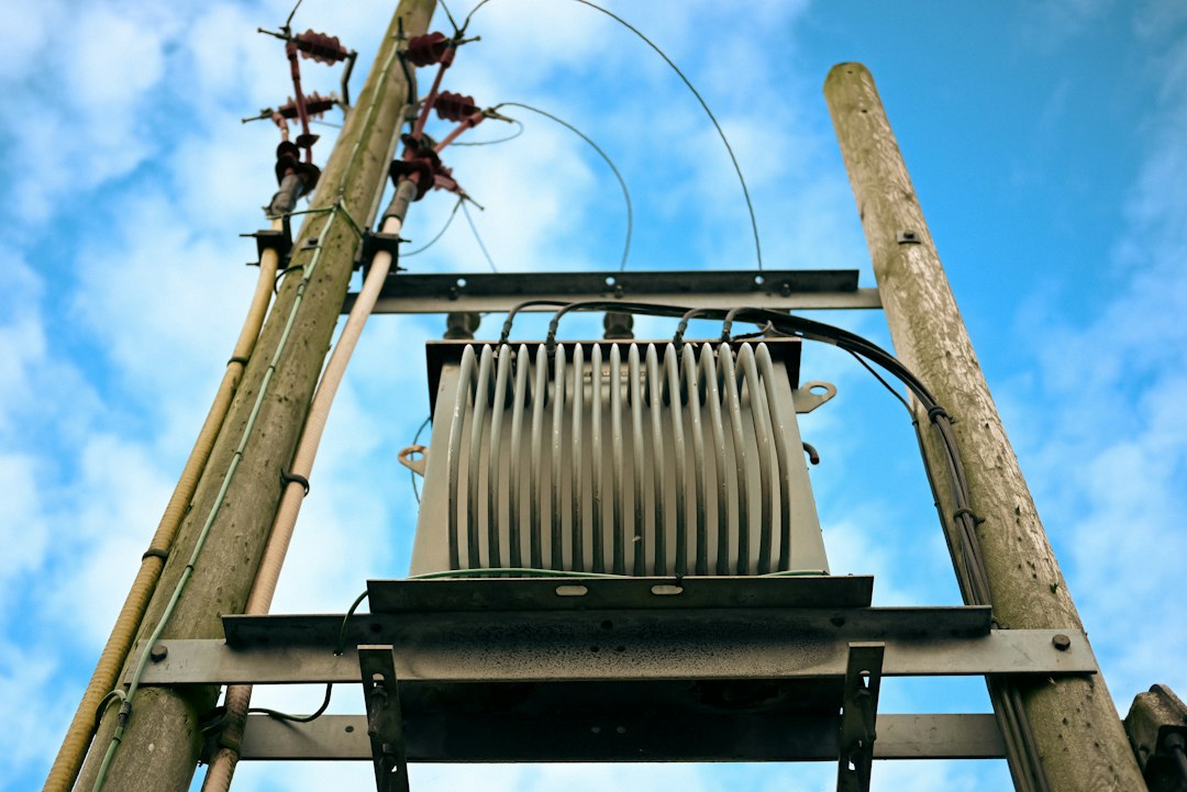
A zig-zag grounding transformer creates an artificial neutral on a delta-connected or otherwise ungrounded three-phase system. When combined with a neutral grounding resistor (NGR), it limits single-line-to-ground current to a deliberate value so protection can detect and clear faults without exposing equipment to an uncontrolled ground-fault duty.
Why an artificial neutral is needed
A delta winding has no accessible neutral. An ungrounded system can continue operating after the first ground fault, but its healthy phases can rise in voltage to ground and intermittent arcing faults can create damaging overvoltages. A grounding transformer provides a controlled zero-sequence path while presenting a high impedance to balanced positive-sequence load current.
How the zig-zag connection works
Each phase is split across two limbs and connected so that normal three-phase flux largely cancels. During a ground fault, zero-sequence currents flow through the windings and combine at the neutral. The arrangement can provide a neutral without the full kVA rating of a conventional load-serving transformer.
A grounding transformer may be:
- A dedicated zig-zag unit with only a neutral function.
- A wye-delta transformer used to create a grounded wye neutral.
- A grounding transformer with an auxiliary secondary for station-service load.
Inputs required before sizing
| Input | Why it matters |
|---|---|
| System line-to-line voltage | Sets neutral-to-ground voltage during a solid ground fault. |
| Target ground-fault current | Controls relay sensitivity, damage and transient overvoltage performance. |
| Fault duration | Determines short-time thermal rating of the transformer and NGR. |
| System charging current | Helps avoid unstable or ineffective high-resistance grounding. |
| Zero-sequence impedance | Affects the actual current delivered through the grounding path. |
| Protection clearing time | Must coordinate with equipment short-time ratings and backup protection. |
| Continuous neutral load | Needed if the transformer also supplies auxiliaries or carries harmonics. |
Step 1: calculate line-to-neutral voltage
For an 11 kV line-to-line system:
VLN = VLL / √3 = 11,000 / 1.732 ≈ 6,351 V
This is the approximate voltage applied across the grounding impedance during a solid phase-to-ground fault, before allowing for transformer and source impedance.
Step 2: choose the ground-fault current
The target is a protection-system decision, not a catalog default. Low-resistance grounding may use hundreds of amperes to obtain selective feeder protection, while high-resistance grounding may limit current to a few amperes or tens of amperes. The selected current must be high enough relative to total system capacitive charging current for stable detection and overvoltage control.
Step 3: calculate the neutral grounding resistor
For a preliminary calculation:
RNGR ≈ VLN / Ig
If the target ground-fault current is 400 A:
RNGR ≈ 6,351 / 400 = 15.88 Ω
The resistor must also have the required time rating. Its initial fault power is:
P ≈ I²R = 400² × 15.88 ≈ 2.54 MW
This is a short-time duty, for example 10 seconds, not a continuous load. The manufacturer must account for hot resistance, temperature rise and permissible tolerance.
Step 4: estimate grounding-transformer short-time kVA
A useful preliminary apparent-power duty is:
SGT ≈ VLN × Ig / 1000
For the 11 kV, 400 A example:
SGT ≈ 6.351 × 400 = 2,540 kVA for the specified fault duration
This does not mean a 2.54 MVA continuous-duty transformer is required. Grounding transformers are commonly specified with a short-time neutral-current rating such as 400 A for 10 seconds. The final winding design, temperature rise and zero-sequence impedance come from the manufacturer.
Step 5: include zero-sequence impedance
The resistor is not the only impedance in the fault loop. Source zero-sequence impedance, grounding-transformer impedance, conductors and the fault itself all affect current. A more complete study uses sequence networks:
If = 3V1 / (Z1 + Z2 + Z0 + 3Zn)
The exact arrangement depends on the system. The grounding transformer manufacturer should state zero-sequence impedance and tolerance, and the protection study should use that value rather than assume the NGR alone sets the current.
Worked design example
Consider an 11 kV industrial bus supplied from a delta source. The protection study requires 400 A maximum ground-fault current for 10 seconds.
- VLN = 11 / √3 = 6.351 kV.
- Preliminary NGR = 6,351 / 400 = 15.88 Ω.
- Initial resistor duty = 2.54 MW for 10 seconds.
- Preliminary grounding-transformer duty = 2,540 kVA for 10 seconds.
- Specify neutral current as 400 A for 10 seconds, subject to the calculated zero-sequence network.
- Verify that backup protection clears within the equipment’s thermal rating.
- Confirm insulation level, impulse withstand, system frequency, altitude and ambient temperature.
What if the grounding transformer supplies auxiliaries?
If a secondary winding supplies station service, the transformer has two simultaneous duties:
- A continuous kVA rating for the auxiliary load.
- A short-time zero-sequence rating for ground faults.
The manufacturer must design for the combined thermal and magnetic duty. Do not add the numbers using a simple arithmetic rule without a thermal design check.
Protection scheme
Typical protection may include:
- Neutral overcurrent element using a CT in the neutral connection.
- Bus or feeder ground-fault elements coordinated with the neutral relay.
- Backup ground-fault protection with a delay below the 10-second thermal limit.
- Temperature or thermal protection for the NGR where provided.
- NGR continuity monitoring to detect an open resistor path.
- Restricted-earth-fault or differential protection where required by the design.
NGR continuity monitoring
An open NGR can silently convert a resistance-grounded system into an ungrounded system. Continuity monitors inject or measure a small signal to confirm the resistor and connection remain intact. Alarm and trip philosophy should be defined: some facilities allow a controlled shutdown, while others trip immediately because loss of grounding invalidates the protection design.
Cable and neutral conductor duty
The neutral conductor between the transformer, NGR and earth must withstand the selected current for the full clearing time. Check short-circuit thermal withstand, mechanical support and insulation. Keep the connection route short and protected against physical damage. The NGR enclosure and grounding transformer tank must be bonded according to the earthing design.
Installation location
Locate the grounding transformer close to the bus it grounds when practical. A long connection adds impedance and creates more opportunities for an open circuit. Outdoor installations require appropriate enclosure, corrosion protection and environmental ratings. Indoor NGRs need adequate ventilation and safe clearance from combustible materials because their short-time temperature can be high.
Parallel sources and multiple grounding transformers
When buses can be coupled, two grounding transformers may operate in parallel and double the available ground-fault current. The switching logic must match the operating modes. Common strategies include:
- Only one grounding transformer connected when buses are coupled.
- Both connected, with protection settings designed for the combined current.
- Each transformer tied to its bus section with automatic interlocking around the coupler.
Every credible breaker position should be represented in the ground-fault study.
Specification checklist
| Item | Specify |
|---|---|
| System data | Voltage, frequency, insulation level and earthing arrangement |
| Neutral duty | Current in amperes and duration in seconds |
| Zero-sequence impedance | Required value or maximum, with tolerance |
| Continuous duty | Auxiliary kVA, if any |
| Environment | Altitude, ambient temperature, indoor/outdoor and enclosure class |
| Tests | Routine tests, impedance verification, temperature or special tests |
| Accessories | CTs, temperature devices, marshalling box and lifting provisions |
| NGR | Ohms, amperes, seconds, insulation, enclosure and monitoring |
Common mistakes
- Calculating the resistor but ignoring grounding-transformer impedance.
- Using the normal load kVA formula as a continuous rating requirement.
- Failing to coordinate backup relay time with the 10-second rating.
- Ignoring system charging current when selecting high-resistance grounding.
- Allowing two grounding transformers to operate after bus coupling without recalculation.
- Omitting NGR continuity monitoring.
- Applying a generic 400 A value without a protection selectivity study.
Frequently asked questions
Can a zig-zag transformer carry normal three-phase load?
A dedicated grounding transformer is not intended to supply ordinary balanced load unless it has a separately designed auxiliary winding and continuous kVA rating.
Why is the short-time kVA so high?
The neutral current flows only during a fault and for a limited duration. The winding is designed for the specified thermal impulse rather than continuous operation at that apparent power.
Can the NGR current equal the relay pickup?
No. Relay pickup must account for fault-current variation, CT performance, system charging current and coordination margins. The protection study determines settings.
Conclusion
A zig-zag grounding transformer and NGR must be designed as one zero-sequence system. Define the target fault current and clearing time, calculate the preliminary resistance and short-time duty, then model all sequence impedances and operating configurations. The final manufacturer data and relay study should prove that the actual current is detectable, selective and within equipment ratings.
Featured photo: Gavin Allanwood via Unsplash. This article provides preliminary engineering guidance; final sizing requires a system study and manufacturer confirmation.