Understanding Medium-Voltage Feeder Panels: A Deep Dive into an MV Single-Line Diagram
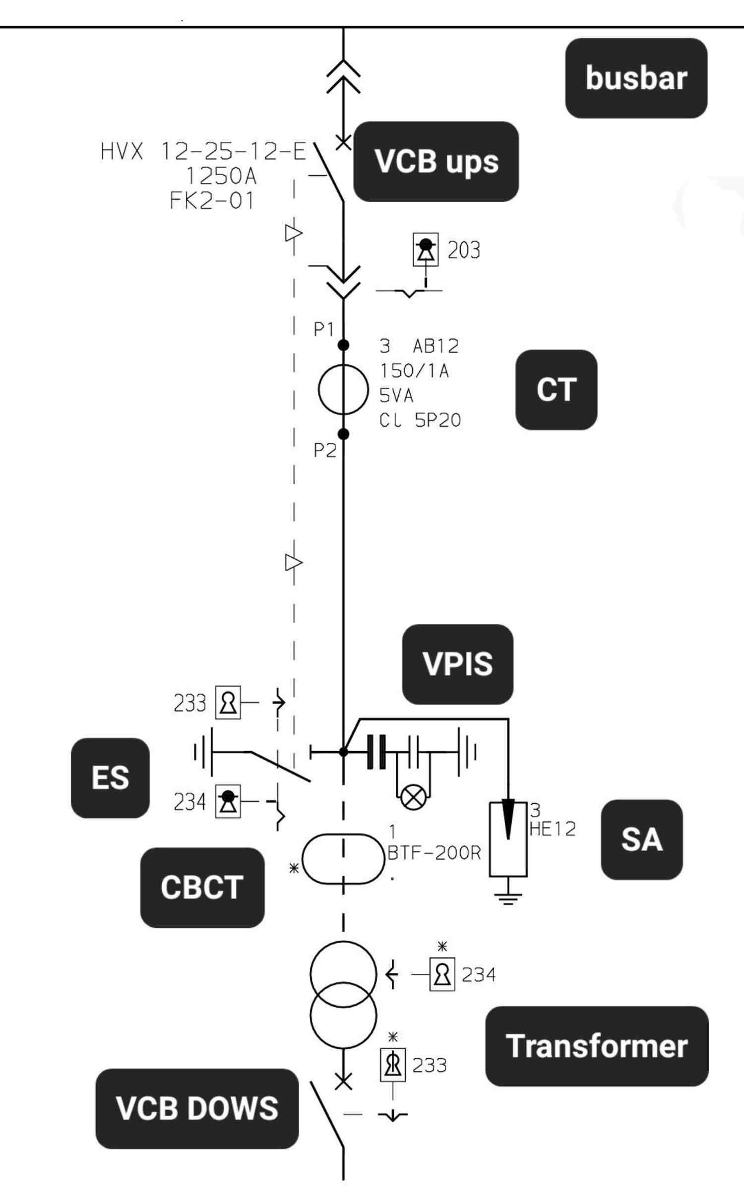
In medium-voltage (MV) electrical distribution, safety, reliability, and precision are paramount. Single-Line Diagrams (SLDs) serve as the ultimate blueprint for engineers and operators, distilling complex three-phase power systems into a clear, single-line representation.
Today, we are breaking down a typical MV outgoing feeder panel—specifically, a vacuum circuit breaker (VCB) cubicle feeding a downstream power transformer. Let’s take a top-to-bottom journey through this SLD to understand the vital components that keep the grid safe and operational.
1. The Main Incomer: Busbar & Vacuum Circuit Breaker
At the very top of our feeder panel sits the Busbar, the backbone supplying power to the entire switchgear line-up. Directly below it is the primary switching device: the Vacuum Circuit Breaker (VCB).
Based on the technical nomenclature on the diagram (HVX 12-25-12-E / 1250A / FK2-01), this is a high-performance Schneider Electric HVX series VCB with the following engineering specifications:
- 12kV Rated Voltage: Designed for standard medium-voltage distribution systems.
- 25kA Breaking Capacity: The maximum fault current the breaker can safely interrupt without catastrophic failure.
- 1250A Continuous Current: The maximum continuous load current the breaker can carry.
- FK2-01: The specific panel/feeder designation for maintenance tracking.
The VCB serves as both a surgical switch for routine operations and a heavy-duty shield capable of extinguishing intense electrical arcs in a vacuum chamber during a short circuit.
2. Measurement & Protection: The Current Transformer (CT)
Moving down the line, we encounter the Current Transformer (CT) labeled 3 AB12. This component steps down massive system currents into small, measurable values for protection relays.
- 150/1A Ratio: If 150 Amps are flowing through the main primary line, the CT outputs exactly 1 Amp at its secondary terminal for the relay to read.
- 5VA Burden: The maximum output capacity (load) the CT can drive without losing accuracy.
- CL 5P20 (Protection Class): * 5P indicates a composite error of no more than $\pm5\%$ at the accuracy limit.
- 20 is the Accuracy Limit Factor (ALF). This means the CT can faithfully replicate massive fault currents up to $20 \times 150\text{A} = 3000\text{A}$ without magnetic saturation, ensuring the protective relay trips accurately during a severe fault.
- P1 / P2: Primary polarity markings that dictate the precise direction of power flow.
3. System Vitality & Surge Defense: VPIS & SA
Further down the line, the system branches off to two crucial safety and asset-protection devices:
Voltage Presence Indicating System (VPIS)
Represented by parallel-line symbols connected to a lamp indicator, the VPIS uses a capacitive voltage divider. It serves as a permanent visual safety check, illuminating a front-panel LED to warn operators if the cable/bus section is energized before they attempt any maintenance.
Surge Arrester (3 HE12)
Connected in parallel to the line just before the cable termination, this set of 3 metal-oxide surge arresters (one per phase) shunts high-voltage transients—such as lightning strikes or switching surges—harmlessly to the ground, shielding the downstream transformer from insulation breakdown.
4. Grounding & The Mechanical Interlock Shield
Safety in MV switchgear is heavily governed by strict mechanical interlocks, preventing human error from causing fatal accidents.
Below the CT sits the Earthing Switch (ES), used to deliberately ground the feeder during maintenance. This switch is mechanically interlocked with the downstream transformer via a Trapped Key Interlocking Scheme (Keys 233 and 234):
- Key 234: You cannot close the earthing switch unless the transformer’s Low Voltage (LV) side is completely isolated. This prevents back-feeding power into an open grounding switch.
- Key 233: Once the MV Earthing Switch is securely closed and locked in the earth position, Key 233 is released. This key must then be walked over to open the downstream transformer enclosure doors. You literally cannot touch the transformer unless the upstream power is mechanically grounded!
5. Advanced Earth Fault Detection: The CBCT
Before the power reaches the transformer, the phase conductors pass through a BTF-200R Core-Balance Current Transformer (CBCT), also known as a zero-sequence or toroidal window-type CT.
Under normal, balanced conditions, the vector sum of the three-phase currents equals zero ($I_a + I_b + I_c = 0$), resulting in no magnetic flux in the CBCT ring. However, the moment an insulation failure occurs and current leaks to earth, this balance is broken. The CBCT instantly detects this zero-sequence current, triggering sensitive earth-fault (SEF) protection before major damage occurs.
6. The Destination: Downstream Transformer & VCB Downstream
Finally, the circuit terminates at the Power Transformer, which steps down the 12kV medium voltage to a usable low voltage for the facility. Directly beneath the transformer, a downstream breaker (VCB DOWS) manages the outgoing secondary loads, completing the power distribution chain.
Summary of Feeder Component Flow
| Component Designation | Primary Function | Key Technical Parameter |
| VCB (HVX 12-25-12-E) | Main Circuit Interruption | 12kV, 25kA breaking capacity |
| CT (3 AB12) | Protection Current Measurement | 150/1A, Class 5P20 |
| VPIS | Visual Live-Line Indication | Capacitive voltage divider |
| Surge Arrester (3 HE12) | Overvoltage Transient Protection | Metal-oxide varistor design |
| Earthing Switch (ES) | Maintenance Safety Grounding | Trapped-key interlocked (233/234) |
| CBCT (BTF-200R) | Sensitive Earth Fault Detection | Toroidal window-type zero-sequence |
Understanding these intricate layers of measurement, protection, and physical interlocking highlights just how robust modern medium-voltage infrastructure is. Every symbol on an SLD represents a critical line of defense keeping both electrical assets and human operators entirely out of harm’s way.