Motor & MCC Earthing – A Clear Specification for Reliability and Safety
When specifying earthing for a 100 kW motor and its associated Motor Control Center (MCC), ambiguity is the enemy of safety. A vague note like “earth adequately” often results in undersized conductors or poor installation practices that lead to nuisance tripping, electrical noise, or, worse, safety hazards.
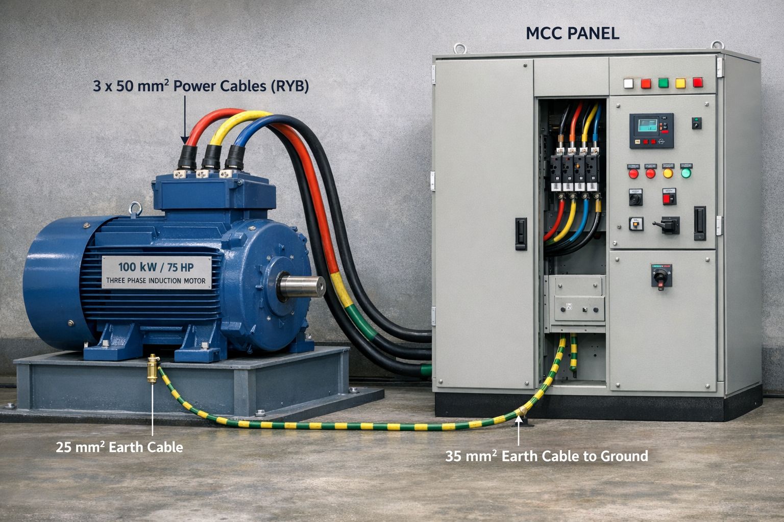
To ensure a robust installation, we need to define the earthing conductors for three distinct elements: the motor body, the MCC panel, and the cable armour. Below is a clear specification based on a 100 kW (≈75 HP), 415 V, 3-phase motor.
The Motor Details
- Rating: 100 kW
- Supply: 415 V, 3-Phase, 50 Hz
- Full Load Current (Approx): 170–180 A
Reference Power Cable: 3.5C × 70 mm² Copper or 3.5C × 120 mm² Aluminium
1. Motor Body Earthing
The primary function of the motor body earth is to provide a low-impedance path for fault current. If a winding insulation failure occurs, this conductor ensures that the chassis does not become live and that the upstream protective device (MCCB or fuse) operates instantly.
Specification:
- Cable: 1 × 35 mm² Copper
- Insulation: Green/Yellow (Double insulated, if required by local codes)
- Connection: From the dedicated motor earth terminal (usually located inside the main terminal box or on the foot) directly to the MCC earth busbar or the plant earth grid.
Rationale:
As per IEC 60364-5-54, the cross-sectional area of the earthing conductor should generally be at least 50% of the phase conductor size when the phase conductor exceeds 35 mm².
- Phase (Cu): 70 mm²
- Earth (Cu): 35 mm² (50% of 70 mm²)
This ensures that the earth conductor can safely carry the full fault current without thermal damage until the protective device clears the fault.
2. MCC Panel Earthing
The MCC panel is the heart of the motor’s control system. It houses sensitive relays, contactors, and the Variable Frequency Drive (if applicable). A high-integrity earth connection is required not only for safety but also for electromagnetic compatibility (EMC) and noise suppression.
Specification:
- Cable: 2 × 35 mm² Copper (Double Earthing)
- Connection: MCC internal earth busbar → Plant earth grid / Earth pit.
Why Double Earthing?
For motor control panels, especially those feeding high-power motors like this 100 kW unit, a single earth path is often considered insufficient. Double earthing (using two separate conductors run in parallel) provides:
- Redundancy: If one connection is damaged or loosens over time due to vibration, the second conductor maintains the integrity of the safety circuit.
- Reduced Impedance: Parallel conductors lower the total impedance to earth, which is critical for quickly clearing high fault currents.
- Compliance: Many industrial standards (such as IS 3043 and specific client specifications) mandate dual earthing for panels with a fault-current capacity above a certain threshold.
3. Cable Armour Earthing (If Armoured Cable Used)
Armoured cables (SWA or STA) are often used in industrial environments to protect against mechanical damage. The metallic armour (steel wire or aluminum tape) acts as a screen and a secondary earth path. However, it must be terminated correctly.
Specification:
- Cable: 25 mm² Copper (Green/Yellow)
- Connection: Both ends (MCC side & Motor side).
Critical Installation Notes:
- At the MCC: The armour shall be terminated via a suitable gland (e.g., CW or Exe gland) and bonded to the earth bar using the 25 mm² Cu fly lead.
- At the Motor: The armour must also be earthed at the motor terminal box. Contrary to some outdated practices, earthing at one end only is insufficient for 415 V systems unless specific circulating current issues are identified (which is rare for standard LV motors). Earthing both ends minimizes touch voltage on the cable surface and provides a parallel earth return path.
4. Earth Pit Recommendation
A cable is only as good as the electrode it connects to. For a 100 kW motor and its MCC, the earth grid connection point must have a low resistance to dissipate energy quickly.
Specification:
- Electrode: Copper Bonded Rod (4.0 mm copper coating, 17.2 mm diameter) or GI Pipe (Class B).
- Earth Resistance: ≤ 1 Ohm
- Maintenance: Earth pits should be provided with inspection chambers and watering arrangements (using Bentonite powder or salt/charcoal) to maintain low resistance, especially in dry seasons.
Summary Table
For quick reference during installation or inspection, use the following specifications:
| Item | Earthing Cable Size | Mandatory Requirement |
|---|---|---|
| Motor Body Earthing | 35 mm² Cu | Connect from the motor terminal to the MCC earth busbar. |
| MCC Panel Earthing | 2 × 35 mm² Cu | Double earthing mandatory for safety and redundancy. |
| Cable Armour Earthing | 25 mm² Cu | Terminate at both MCC and motor ends. |
| Earth Resistance | ≤ 1 Ω | Connect from the motor terminal to the MCC earth busbar. |
Conclusion
Earthing is not merely a regulatory checkbox; it is the foundation of your electrical system’s safety and operational stability. For a 100 kW motor, using a 35 mm² Cu for the motor body, dual 35 mm² Cu for the MCC, and ensuring the armour is bonded with 25 mm² Cu at both ends provides a robust, fault-tolerant system that complies with IEC 60364 and modern engineering best practices.
Disclaimer: Always refer to your site’s electrical drawings and local electrical codes (NEC, IEC, or local standards) before finalizing installations, as fault levels and soil conditions may require adjustments.