Fundamentals of Earthing System Design: Concepts and Analytical Methodology
Abstract
This document presents a structured exposition of the core principles governing the design of electrical earthing (grounding) systems for substations. It elucidates key design concepts through analytical examples and computational results, with a focus on safety performance metrics and mitigation strategies.
1. Introduction
This tutorial outlines the fundamental concepts employed in the design of substation earthing systems. It defines essential terminology, including Grid Potential Rise (GPR), touch voltage, step voltage, and fault current distribution. The behaviour of exemplar earthing systems under fault conditions is examined to demonstrate the application of these concepts.
2. Grid Potential Rise (GPR)
Figure 1(a) depicts a simplified earthing system comprising a square grid of horizontal buried conductors and vertical earth rods. The figure illustrates the resultant surface potential distribution when a fault current energises the system.
When current is injected into the earth via an earthing system, it encounters a resistance primarily determined by soil resistivity. The resulting voltage developed between the earthing system and a remote earth reference point is defined as the Grid Potential Rise (GPR). The GPR is expressed as:
GPR = If * Rg
where ( If ) is the current injected into the earth and ( Rg ) is the resistance of the earthing system.
GPR is directly proportional to both the injected current magnitude and the effective soil resistivity. Accurate in-situ soil resistivity measurements are therefore critical for reliable design. For a given fault current, GPR is approximately inversely proportional to the grid area, with secondary influences from grid shape and burial depth. For the system in Figure 1, the calculated GPR is 2220 V, with a maximum surface potential of 2060 V.
3. Touch and Step Voltages
The earth’s surface potentials are non-uniform and are always lower than the GPR. The potential difference between the energised earthing system and a point on the earth’s surface where a person may stand while contacting a connected metallic structure is termed the touch voltage. The maximum touch voltage for a typical grid often occurs at its corners due to higher current density in perimeter conductors. The potential difference between two points on the Earth’s surface separated by a one-metre stride is defined as the step voltage. Step voltages are generally lower than touch voltages and are of primary concern outside the grid perimeter, where potential gradients are steepest.
These hazardous voltages are proportional to both the injection current and soil resistivity. Design safety is evaluated by comparing computed touch and step voltages against tolerable limits derived from standards such as IEC and IEEE [1, 2]. Mitigation strategies include: (i) reducing actual surface potentials, or (ii) increasing tolerable limits by installing high-resistivity surface layers.
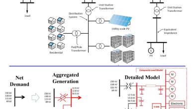
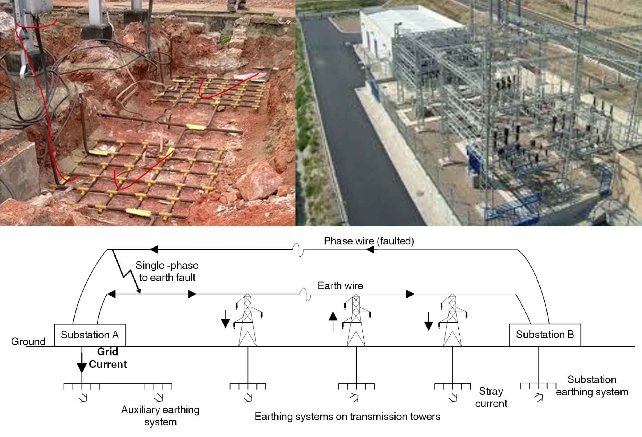
4. Fault Current Distribution
During an earth fault, current returns to the source via all available parallel paths. The relative impedance of each path governs the distribution:
- Earth Wires (Shield Wires): A portion returns entirely via overhead earth wires.
- Substation Earthing System: A portion, termed the grid current (IG), is injected into the earth at the local substation grid.
- Auxiliary Earthing Systems: Additional paths, such as remote earths or reinforced concrete foundations, may carry a portion.
The grid current (IG) is responsible for the local GPR. Accurate design requires analysis of this distribution, though the grid current is typically a fraction of the total fault current.
5. Design to Reduce GPR
A primary design objective is often to limit GPR, typically to levels such as 5000 V for equipment protection [3]. This is achieved by minimising grid resistance (Rg). The most effective methods are:
- Increasing the grid area.
- Installing rods that penetrate lower-resistivity soil strata.
Adding internal grid conductors results in a smaller reduction.
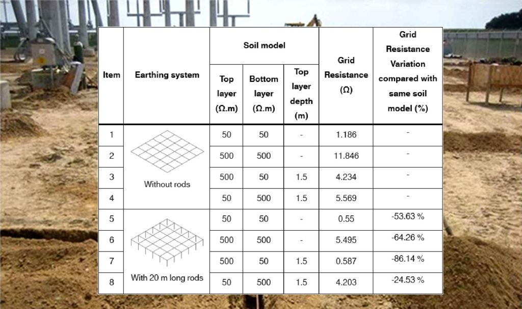
Table 1 presents simulation results for a 20m × 20m grid in uniform 100 Ω·m soil, demonstrating the comparative efficacy of these methods. Note that reducing (R_g) may increase the grid current (I_G), partially offsetting the reduction in GPR.
6. Design to Reduce Touch and Step Voltages
The design must ensure touch voltages within the substation remain below safe limits. This is achieved by making the surface potential approach the GPR, which is accomplished by increasing mesh density. Step voltages within the grid are usually acceptable if touch voltages are controlled. External step voltages can be mitigated by increasing the grid area or installing perimeter grading rings.
7.0 Effects of Soil Resistivity Structure
Soil is typically non-uniform and is best modelled as horizontal layers. Two fundamental two-layer models are:
- High-on-Low (H-L): High-resistivity layer over a low-resistivity layer.
- Low-on-High (L-H): Low-resistivity layer over a high-resistivity layer.
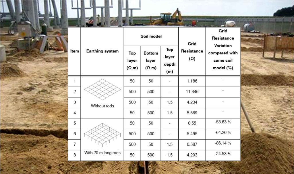
For an H-L model (Figure 8), current seeks the lower layer, often creating a steeper surface gradient and higher touch voltages, despite a lower GPR. For an L-H model (Figure 9), current is confined to the upper layer, leading to a higher GPR and generally more uniform, but elevated, surface potentials. The bottom-layer resistivity predominantly influences GPR, while the top layer significantly affects touch-voltage profiles.
8. Using Rods to Improve Safety
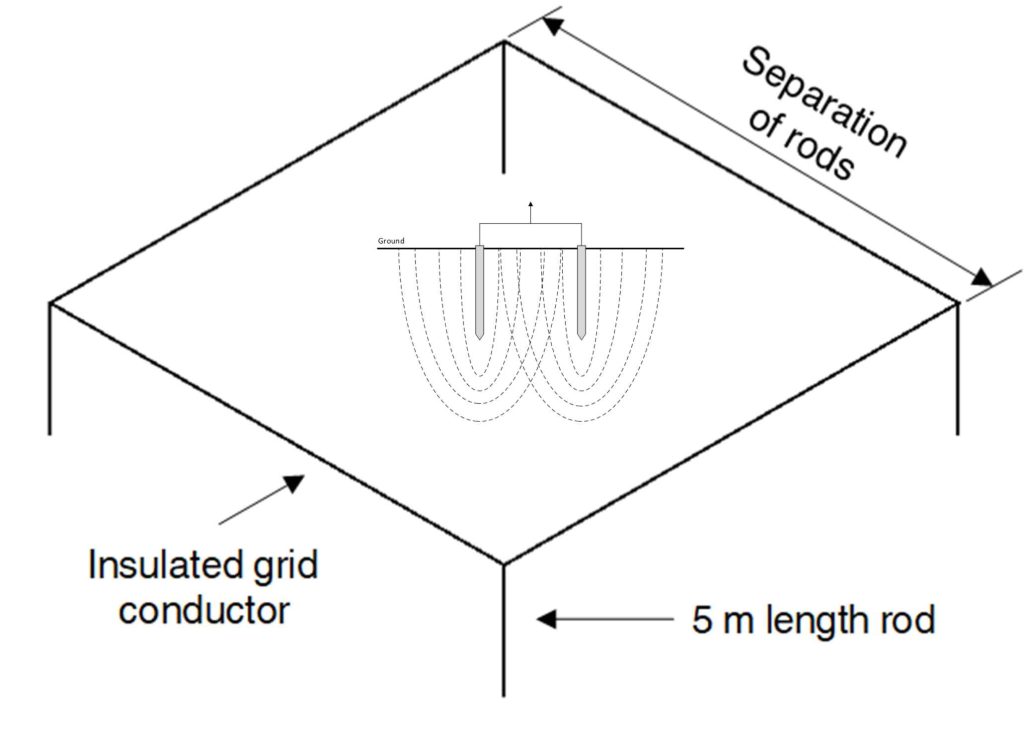
8.1 Rod Separation and the Proximity Effect
The effectiveness of parallel rods is diminished by mutual interference, known as the proximity effect of a grid with varying rod spacing. The Figure shows that rod resistance decreases significantly as spacing increases up to approximately one rod length. For optimal effectiveness, rods should be spaced at least their length apart.
8.2 Optimising Rod Deployment Based on Soil Characteristics
The efficacy of rods varies with soil structure. In H-L soil, rods penetrating the low-resistivity bottom layer dramatically reduce grid impedance (e.g., -86.14%). In L-H soil, rods are less effective (e.g., -24.53%) as current remains in the shallow layer. For L-H soils, extending the grid area via counterpoise conductors is often a more effective strategy than adding rods.