Earthing Integration of Reinforced Concrete Structures in Electrical Substations
Abstract
This document outlines a standardized methodology for the modelling and electrical integration of steel reinforcement within concrete slabs and foundations in high-voltage substation environments. When intentionally bonded to the primary earthing grid, this reinforcement provides a cost-effective enhancement to the overall earthing system’s performance and safety.
1. Introduction: Structural Steel as a Complementary Earth Electrode
Electrical switchgear within substations is frequently mounted on reinforced concrete slabs or foundations. The embedded steel reinforcement, when made electrically continuous and bonded to the central earthing system, functions as an extended earth electrode. Its extensive surface area and high conductivity offer a significant parallel path to earth, improving fault current dissipation and reducing overall earth impedance.
2. Electrical Bonding Methodology
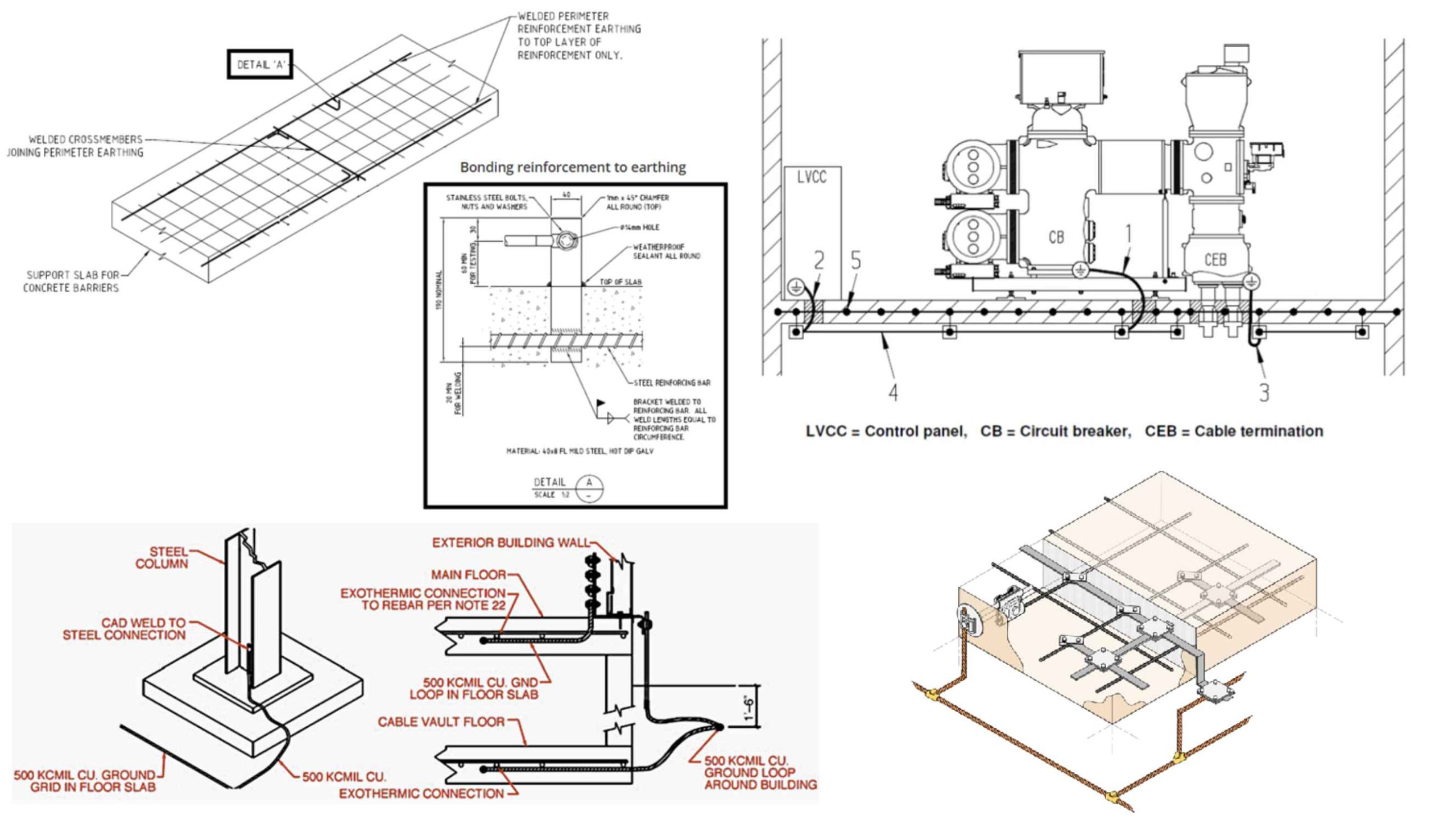
To integrate the reinforcement, the steel rebar network is welded to form an electrically contiguous mesh. Dedicated connection points (often termed “flags” or “tails”) are welded to this mesh and subsequently bolted to the earthing terminals of the supported electrical equipment, such as switchgear. This establishes a low-impedance path, ensuring that during an earth fault, current is efficiently conducted from the equipment into the reinforcement matrix for dissipation into the surrounding earth.
3. Electrical Modelling of Buried Concrete Elements
3.1. Concrete Resistivity: Buried or ground-contacting concrete absorbs ambient moisture, resulting in an electrical resistivity approximating that of the surrounding soil. This equivalence arises because the resistivity of both media is predominantly governed by moisture content and ionic concentration. Consequently, in earthing software models, the concrete volume can be assigned the resistivity value of the adjacent soil, negating the need for a distinct, complex material layer.
3.2. Reinforcement Modelling: The high-conductivity steel reinforcement, with its substantial cross-sectional area, is minimally affected by the encapsulating concrete, provided it covers a comparable spatial extent. In modelling, it is critical to include the reinforcement only when its connection to the main earthing grid is confirmed. Accurate representation focuses on modelling the total geographical area covered by the rebar network rather than simulating the intricate details of individual mesh geometries.
4. Modelling of Control Building Floors
4.1. Equipotential Assumption: Concrete floors within control buildings, whose reinforcement is bonded to the main earth grid, may be considered equipotential surfaces. This assumption validates that during an earth fault, hazardous touch potentials between earthed equipment inside the building are effectively mitigated, and step potentials are rendered safe.
4.2. Modelling Guidelines:
* Ground-level or basement floors with bonded reinforcement should be included in the earthing system model to capture performance and safety metrics accurately.
* For elevated floors in multi-storey buildings where reinforcement is bonded, explicit modelling is typically unnecessary due to the equipotential condition, though the bonding must be verified.
* Compliance with all applicable local standards and equipment manufacturer specifications (e.g., for Gas-Insulated Switchgear/GIS, which may mandate specific reinforcement practices) is imperative.
Figure 2: Earthing detail for GIS switchgear connected to floor reinforcement.
5. Safety Mitigation: Perimeter Grading Ring
A buried grading ring conductor should be installed around and electrically separated from the perimeter of external concrete slabs. This ring mitigates hazardous touch potentials that could arise between the slab (which may rise in potential during a fault) and the adjacent native earth where a person might stand.
6. Conclusion
The deliberate bonding of reinforcement in concrete slabs and foundations to the main earthing grid justifies its inclusion in comprehensive earthing models. Such modelling should treat the concrete as having resistivity equivalent to that of the surrounding soil and prioritize representing the reinforcement’s spatial coverage over its geometric intricacy. For bonded floors within control buildings, the equipotential premise often simplifies or eliminates the need for detailed modelling, provided the electrical connection is verified. This integrated approach enhances the fidelity of safety assessments and optimizes the performance of the earthing system.