كتاب «السيارات الكهربائية» للدكتورة كاميليا يوسف محمد
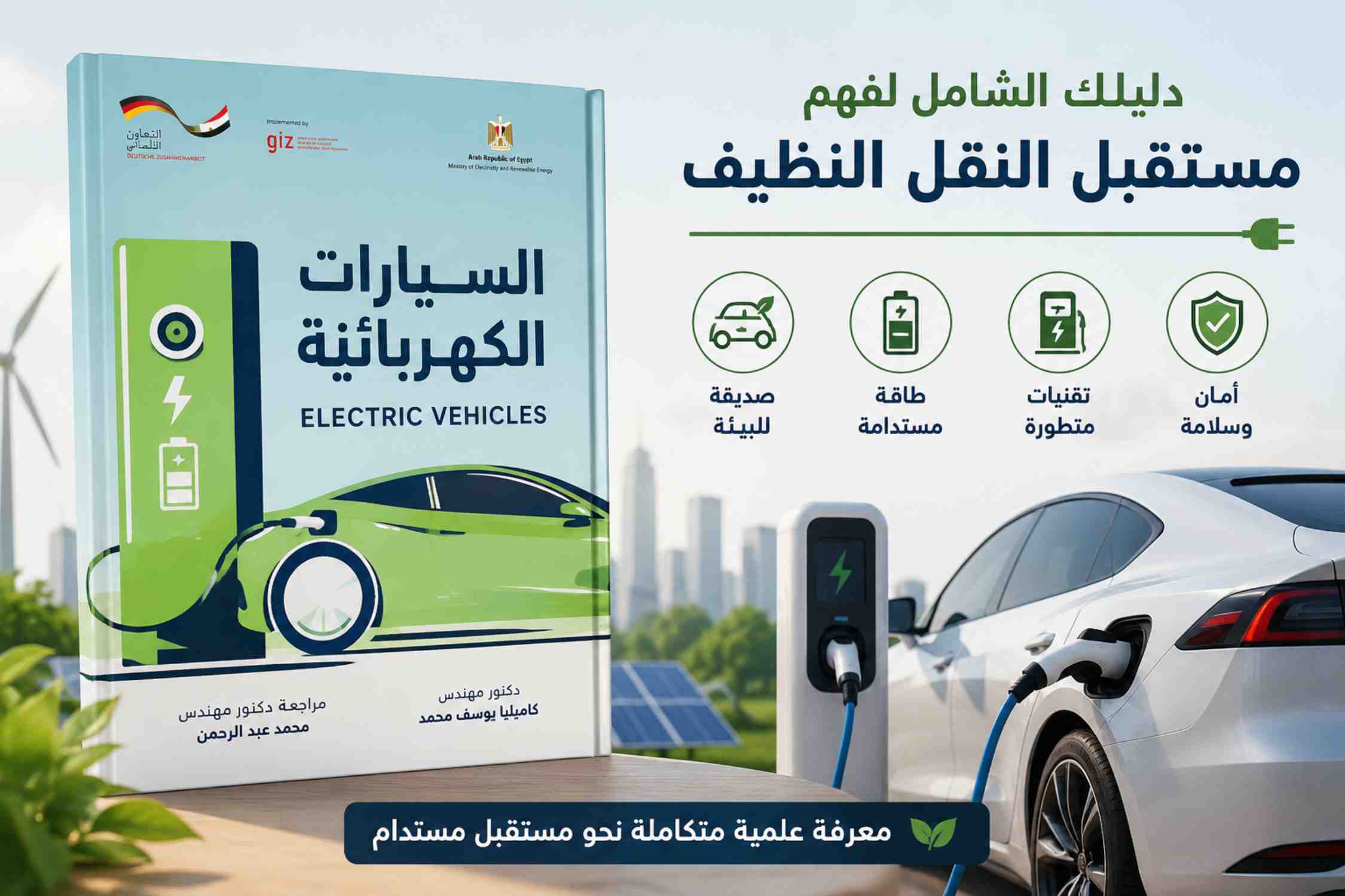
يُعد كتاب «السيارات الكهربائية» للدكتورة المهندسة كاميليا يوسف محمد من أهم المراجع العربية المتخصصة التي تناولت تكنولوجيا السيارات الكهربائية بصورة علمية وعملية شاملة، حيث يقدم للقارئ العربي معرفة متكاملة حول مفهوم المركبات الكهربائية وتطورها وأنواعها ومكوناتها وآليات تشغيلها، إضافة إلى قضايا الشحن والطاقة والأمان والسلامة.
تكمن أهمية هذا الكتاب في أنه جاء في وقت يشهد فيه العالم تحولًا كبيرًا نحو الطاقة النظيفة وتقليل الاعتماد على الوقود الأحفوري، نتيجة التحديات البيئية والتغيرات المناخية التي تهدد مستقبل الكوكب. وقد أشار الكتاب إلى أن السيارات الكهربائية أصبحت من أهم الوسائل التي تساعد على خفض الانبعاثات الضارة وتحقيق التنمية المستدامة، مما يجعلها محورًا رئيسيًا في مستقبل النقل الحديث.
ومن أبرز جوانب أهمية الكتاب أنه لا يقتصر على التعريف النظري بالسيارات الكهربائية، بل يقدم شرحًا تفصيليًا لمكوناتها الأساسية مثل البطاريات والمحركات الكهربائية وأنظمة التحكم ووحدات تحويل الطاقة، إضافة إلى شرح أنظمة الشحن المختلفة، سواء السلكية أو اللاسلكية، مع توضيح مميزات وعيوب كل نظام. كما يعرض الكتاب أنواع السيارات الكهربائية والهجينة وآلية عمل كل منها بأسلوب مبسط يدعم الفهم العلمي والتطبيقي.
كما يبرز الكتاب أهمية السيارات الكهربائية في الحفاظ على البيئة، إذ يوضح أنها لا تنتج عوادم ملوثة أثناء التشغيل، وتتميز بانخفاض الضوضاء وتقليل تكاليف الصيانة مقارنة بسيارات الاحتراق الداخلي التقليدية. كذلك يناقش دورها في تقليل استهلاك الوقود الأحفوري وخفض الانبعاثات الكربونية، وهو ما يتماشى مع التوجهات العالمية نحو الاقتصاد الأخضر والطاقة المتجددة.
ويتميز الكتاب أيضًا بأنه كُتب باللغة العربية مع استخدام المصطلحات الفنية باللغة الإنجليزية، مما يجعله مرجعًا علميًا مهمًا للمهندسين والطلاب والفنيين والباحثين في مجال الطاقة والنقل الكهربائي. وقد حرصت المؤلفة على تبسيط المعلومات العلمية لتكون مناسبة للمتخصصين وغير المتخصصين، مما يساهم في نشر الوعي المجتمعي بثقافة السيارات الكهربائية وتطبيقاتها المختلفة.
إضافة إلى ذلك، يعكس الكتاب اهتمام الدولة المصرية وقطاع الكهرباء والطاقة المتجددة بتوطين صناعة السيارات الكهربائية ونشر ثقافة استخدامها، حيث أشار إلى خطط مصر لدعم الطاقة المتجددة وإنشاء البنية التحتية لمحطات الشحن وتطوير شبكات الكهرباء بما يتوافق مع رؤية مصر 2030 للتنمية المستدامة.
وفي الختام، فإن كتاب «السيارات الكهربائية» للدكتورة كاميليا يوسف محمد يمثل مرجعًا عربيًا متكاملًا يجمع بين الجانب العلمي والتقني والبيئي، ويساهم في نشر المعرفة الحديثة المتعلقة بالمركبات الكهربائية، كما يدعم توجه المجتمعات نحو استخدام وسائل نقل نظيفة وآمنة ومستدامة، مما يجعله من الكتب المهمة لكل مهتم بمستقبل الطاقة والنقل الحديث.