Comprehensive Guide to Electrical Testing of Current Transformers (CTs)
Current Transformers (CTs) are critical components in electrical power systems, serving as the interface between high-voltage primary circuits and low-voltage secondary monitoring or protection equipment. They scale high primary currents down to manageable levels (typically 5A or 1A) for meters, relays, and control devices. Ensuring the accuracy and reliability of CTs through systematic testing is essential for precise billing and effective system protection.
The Importance of CT Testing
The performance of a CT directly impacts the safety and financial integrity of a power system. Testing before commissioning and during routine maintenance helps mitigate risks such as:
- Operational Errors: Preventing the misapplication of metering CTs for protection purposes or vice versa.
- Connection Integrity: Identifying incorrect wiring or reversed polarities before they cause system malfunctions.
- Condition Monitoring: Detecting early signs of insulation degradation or winding damage due to aging or environmental stress.
The following six electrical tests are industry standards for verifying CT performance and maintaining service reliability.
1. Ratio Test
The Ratio Test verifies the relationship between the primary current input and the secondary current output. It ensures that the CT transforms current according to its nameplate specification across all available taps.
| Parameter | Description |
| Definition | The ratio of primary current to secondary current at full load (e.g., 300:5). |
| Formula | N2 / N1 = V2 / V1 (where N is the number of turns and V is the induced voltage). |
| Method | Voltage injection on the secondary side while measuring the induced primary voltage (staying below saturation). |
Warning: Exercise extreme caution to avoid applying voltages that exceed the CT’s saturation point during this test, as it will lead to inaccurate readings and potential equipment stress.
2. Polarity Test
The Polarity Test confirms the relative instantaneous direction of current flow between the primary and secondary windings. Proper polarity is vital for the correct operation of directional relays and power meters.
- Standard Designations: Primary terminals are marked H1 (source) and H2 (load); secondary terminals are marked X1 and X2.
- Verification Method: While modern equipment automates this, a manual “flick test” using a 9V battery and an analog voltmeter is a common field practice.
- Significance: If polarity is reversed, devices like watt-hour meters will run backward, and differential protection relays may trip under normal load conditions.
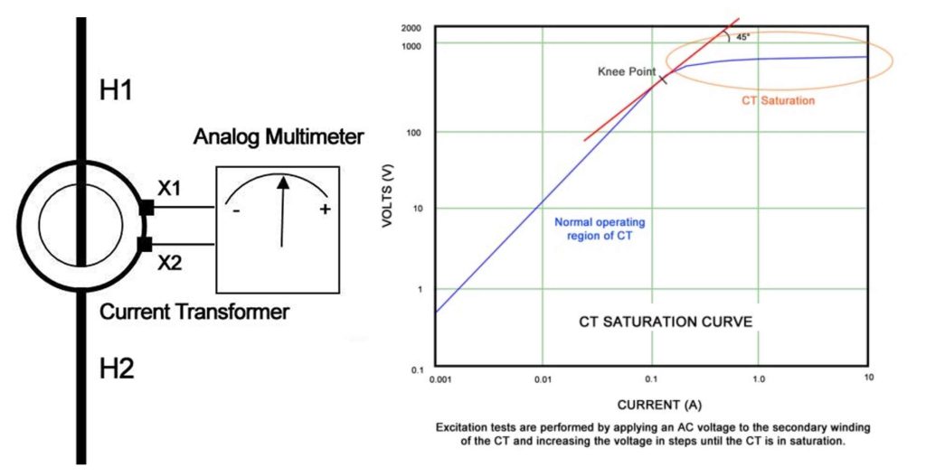
3. Excitation (Saturation) Test
The Excitation Test identifies the “knee point” of the CT—the threshold beyond which the magnetic core saturates and the CT can no longer produce a secondary current proportional to the primary current.
- Procedure: Apply an increasing AC voltage to the secondary winding with the primary open-circuited.
- Data Analysis: Plot the results on a log-log scale. The “knee point” is defined by the IEEE as the point at which a 10% increase in voltage results in a 50% increase in exciting current.
- Purpose: This test confirms the CT’s accuracy class and ensures there are no shorted turns within the windings.
4. Insulation Resistance Test
This test evaluates the dielectric integrity of the CT’s insulation system. It is performed to ensure that the windings are electrically isolated from each other and from the ground.
| Test Configuration | Purpose |
| Primary to Secondary | Verifies insulation between high-voltage and low-voltage circuits. |
| Primary to Ground | Ensures the high-voltage winding is isolated from the chassis/earth. |
| Secondary to Ground | Ensures the low-voltage winding is isolated from the chassis/earth. |
Key Considerations:
- Minimum Standards: For 600V class CTs, a minimum of 1000VDC is applied, with a generally accepted minimum resistance of 1 MΩ (though NETA recommends >500 MΩ for new equipment).
- Trending: The absolute value is less important than the trend over time; a sudden drop indicates insulation failure.
5. Winding Resistance Test
The Winding Resistance Test measures the DC resistance of the CT secondary windings. This value is used to calculate the actual internal burden and to detect issues like loose connections or shorted turns.
- Measurement: Requires a high-precision low-resistance ohmmeter (DLRO) due to the very low resistance values involved.
- Maintenance Tip: Always demagnetize the CT after performing a DC resistance test, as the DC current can leave residual magnetism in the core, affecting future accuracy.
6. Burden Test
The Burden Test measures the total impedance of the secondary circuit connected to the CT, including meters, relays, and wiring.
- Objective: To ensure the total connected load (burden) does not exceed the CT’s rated burden capacity.
- Consequences of Over-Burdening: If the burden is too high, the CT may saturate prematurely during a fault, leading to inaccurate relay operation or metering errors.
- Verification: This test also confirms that the secondary circuit is properly grounded at a single point and that no shorting blocks have been left closed.
Summary of Testing Objectives
| Test Type | Primary Objective | Critical For |
| Ratio | Accuracy Verification | Billing & Protection |
| Polarity | Directional Accuracy | Power Metering & Relays |
| Excitation | Core Integrity | Fault Performance |
| Insulation | Dielectric Strength | Safety & Longevity |
| Resistance | Winding Integrity | Internal Loss Calculation |
| Burden | Circuit Compatibility | System Accuracy |