Characteristics of Power System Neutral Grounding Techniques: Fact and Fiction
The selection and application of power system grounding techniques remain one of the most critical and often misunderstood aspects of electrical system design. This article, based on a comprehensive application paper, reviews the characteristics of various neutral grounding methods—including solidly grounded, ungrounded, low-resistance grounded (LRG), and high-resistance grounded (HRG) systems—as they are applied in industrial and commercial settings. The discussion focuses on the trade-offs between fault current magnitude, system voltage stability, continuity of service, and the critical issue of transient overvoltages. By clarifying the operational realities and code requirements, this analysis provides a basis for informed selection to enhance system reliability and safety.
1. Introduction and Historical Context
The practice of power system grounding has evolved significantly since the early 20th century, when only two primary methods were considered: solidly grounded and ungrounded systems. While solid grounding offered high fault current to ensure rapid operation of protective devices, it introduced disadvantages such as potential hazards from arcs in certain environments and reduced service continuity. Conversely, ungrounded systems were favored for their perceived ability to maintain service through a single ground fault.
Modern power systems engineering has introduced impedance grounding techniques, primarily utilizing resistance or reactance, to provide alternatives that balance safety, equipment protection, and service continuity. The fundamental choice of grounding method is heavily influenced by two key questions :
- Are there any line-to-neutral loads?
- How important is service continuity for this electrical system?
The presence of line-to-neutral loads strongly suggests solid grounding, while high continuity requirements point toward ungrounded or high-resistance grounded systems.
2. Regulatory Framework and Fundamental Definitions
In industrial and commercial applications, power system grounding design is largely governed by Article 250 of the National Electrical Code (NEC). The NEC’s primary objective for system grounding is twofold: to limit voltages caused by external events (such as lightning or line surges) and to stabilize the voltage to ground during normal operation. For equipment grounding, the goal is to limit the voltage to ground on metallic enclosures and to facilitate the operation of overcurrent devices during ground faults.
To establish a common technical perspective, the following definitions, primarily sourced from the IEEE “Green Book” (IEEE Std. 142-1982), are essential :
| Term | Definition |
| Ungrounded System | A system without an intentional connection to ground, except through very high-impedance devices. It is coupled to ground through the distributed capacitance of its phase windings and conductors. |
| Grounded System | A system where at least one conductor or point (usually the neutral) is intentionally grounded, either solidly or through an impedance. |
| Grounded Solidly | Connected directly through an adequate ground connection with no intentional impedance inserted. |
| Resistance Grounded | Grounded through an impedance whose principal element is resistance. |
| Inductance Grounded | Grounded through an impedance whose principal element is inductance. |
| Effectively Grounded | Grounded through a sufficiently low impedance such that the ratio of zero-sequence reactance to positive-sequence reactance ($X_0/X_1$) is positive and less than 3.0, and the ratio of zero-sequence resistance to positive-sequence reactance ($R_0/X_1$) is positive and less than 1.0. |
3. Comparison of Solidly Grounded and Ungrounded Systems
The differences between solidly grounded and ungrounded systems represent the extremes of grounding practice, particularly under a sustained (bolted) line-to-ground fault condition.
Solidly Grounded Systems
Solid grounding, often mandated by the NEC for systems below 1000 V that can be grounded, is characterized by a direct connection of the system neutral to ground, ensuring that the maximum voltage to ground on the ungrounded conductors does not exceed 150 V.
- Fault Current: Extremely high ground-fault current is available (e.g., 29,200 A for a typical 480 V system), ensuring rapid operation of protective devices.
- System Voltage: The voltage on the faulted phase collapses to zero, and the voltages on the unfaulted phases remain at the normal line-to-ground value ($V_{L-N}$). The system voltage is suppressed.
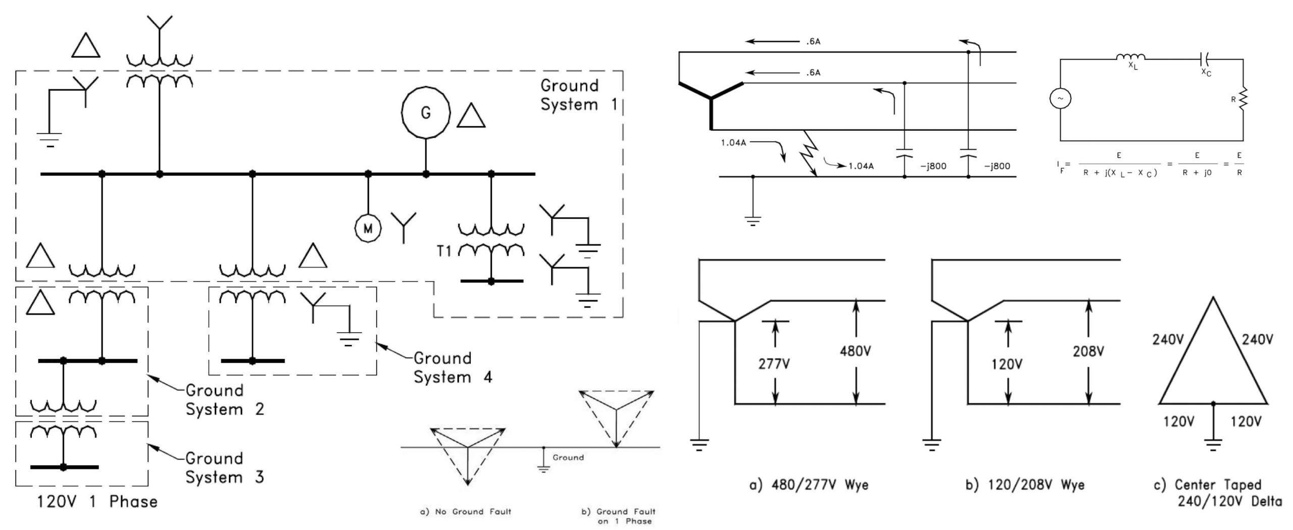
Ungrounded Systems
In an ungrounded system, a ground fault does not provide a direct path back to the source neutral. The fault current must return through the system’s distributed capacitance to ground.
- Fault Current: The available ground-fault current is very low (e.g., 1.04 A for a typical 480 V system), often too low to trip protective devices, thereby allowing service continuity through the first fault.
- System Voltage: The voltage on the faulted phase collapses to zero, but the voltages on the two unfaulted phases rise from the normal line-to-ground value (VL-N) to the full line-to-line value (VL-L). This places significant stress on the insulation of the unfaulted phases.
The Transient Overvoltage Hazard
The most significant drawback of ungrounded systems is the potential for transient overvoltages caused by intermittent or restriking ground faults. When an arcing fault occurs, the arc extinguishes and restrikes, leaving a trapped direct current (DC) charge on the system’s shunt capacitance. With no path to dissipate this charge, the system’s neutral point is displaced. The subsequent restriking of the arc can cause the system voltage to oscillate, leading to transient overvoltages that can reach 550% to 700% of the normal line-to-neutral voltage. These high-magnitude, high-frequency surges accelerate insulation deterioration and can cause multiple equipment failures across the entire system.
4. Impedance Grounding Techniques
Impedance grounding methods insert a controlled impedance (a resistor or reactor) between the system neutral and ground to mitigate the disadvantages of the two extreme grounding systems.
Inductance Grounding
Inductance grounding, which uses a reactor to limit fault current, is rarely used in industrial settings. While it can limit fault current, the inductive reactance can resonate with the system’s shunt capacitance during arcing faults, leading to very high transient overvoltages, similar to those in an ungrounded system. To control these transients, studies indicate that the design must permit at least 60% of the three-phase short-circuit current to flow, resulting in fault currents that are often too high for practical application.
Resistance Grounding
Resistance grounding, which uses a resistor to limit fault current, effectively damps transient overvoltages, eliminating the phenomenon that plagues ungrounded systems.
Low Resistance Grounding (LRG)
LRG systems are typically applied to medium-voltage systems (above 1 kV), where high capital investment necessitates rapid fault clearing.
- Fault Current: Limited to a range of 200 A to 1200 A. This current is sufficient to reliably operate protective devices and trip the faulted circuit off-line, but low enough to minimize damage at the fault point.
- Application: Not recommended for low-voltage systems (under 1000 V) because the voltage drop across the resistor can be too high, preventing reliable current flow through the fault arc for detection.
High Resistance Grounding (HRG)
HRG systems are the modern alternative to ungrounded systems, offering service continuity while controlling transient overvoltages.
- Fault Current: Limited to 10 A or less. This current is low enough to prevent appreciable damage at the fault point, allowing the faulted circuit to remain online temporarily.
- Transient Control: The resistor continuously dissipates the trapped DC charge left by an arcing fault, effectively maintaining a stable neutral point and preventing the buildup of destructive transient overvoltages.
- Maintenance: HRG systems are safer and more reliable than ungrounded systems because they facilitate easier fault location. A common variation uses a pulsing contactor to momentarily vary the fault current (e.g., 4 A to 7 A), allowing maintenance personnel to use a sensitive clamp-on ammeter to trace the pulsed current and pinpoint the fault location without de-energizing any loads.
5. Grounding Transformers for Delta Systems
When a system’s source is delta-connected, a neutral point is not naturally available for grounding. In such cases, a grounding transformer is used to derive a neutral. This can be accomplished using:
- Three Auxiliary Transformers (Wye-Broken Delta): Three single-phase transformers are connected wye on the primary and broken delta on the secondary. A resistor is inserted in the broken delta leg. Under normal conditions, the secondary voltages sum to zero, and no current flows through the resistor. Under a ground fault, the vector sum is non-zero, and the resistor limits the reflected primary fault current.
- Zig-Zag Grounding Transformer: This transformer uses a special winding configuration to create a neutral point. It appears “transparent” to the system under normal conditions but provides a path for zero-sequence current during a ground fault. A resistor is connected between the derived neutral and ground to achieve resistance grounding.
6. Technical Summary and Selection Criteria
The selection of a grounding method must be a deliberate process that considers the system’s voltage level, load characteristics, and required service continuity. Table 1 summarizes the characteristics of the various grounding methods typically used in industry.
| Characteristic | Ungrounded | Solidly Grounded | Low Resistance | High Resistance |
| Current for L-G Fault | Less than 1% of 3the -phase fault current | 100% or greater | 5% to 20% | Less than 1% |
| Transient Overvoltages | Very high | Not excessive | Not excessive | Not excessive |
| Automatic Segregation | No | Yes | Yes | No |
| Lightning Arresters | Ungrounded neutral type | Grounded-neutral type | Ungrounded neutral type | Ungrounded neutral type |
| Remarks | Not recommended due to overvoltages and non-segregation of fault. | Generally used on systems 600 V and below, and over 15 kV. | Best suited for industrial systems of 2.4 kV to 15 kV. | Generally used on systems 5 kV and below. |
Table 1. System Characteristics with Various Grounding Methods
For systems requiring high service continuity, the options are limited to ungrounded and high-resistance grounded systems, as all others require automatic segregation (tripping) of the faulted zone. However, given the severe transient overvoltage risk, the High Resistance Grounded (HRG) system is the preferred choice for maximizing service continuity while maintaining system integrity and safety.
Conclusion
Properly selected and implemented system grounding is a cornerstone of reliable and safe electrical power system operation. The choice between grounding methods is a balance between fault current magnitude, system voltage stability, and the need for service continuity. While solid grounding is often mandated by code for low-voltage systems, the HRG system offers a superior alternative to an ungrounded system for applications requiring high continuity, effectively eliminating destructive transient overvoltages while allowing the location and clearing of the first ground fault without service interruption. Retrofitting existing delta systems with grounding transformers allows engineers to leverage the benefits of resistance grounding, thereby significantly improving overall system reliability and safety .