Types of Feeders Used for Electrical Distribution
In electrical power systems, feeders play a crucial role in transmitting electricity from generating stations or substations to distribution points. A feeder is essentially a power line designed to carry electrical energy without any intermediate tapping, meaning the current remains the same from the sending to the receiving end. Feeders are responsible for delivering power efficiently to the main load centers while maintaining a stable voltage supply. Different types of feeder systems are used in electrical distribution networks depending on reliability, cost, and load requirements. The four major feeder systems are:
- Radial Feeders
- Parallel Feeders
- Ring Main Feeders
- Interconnected Systems
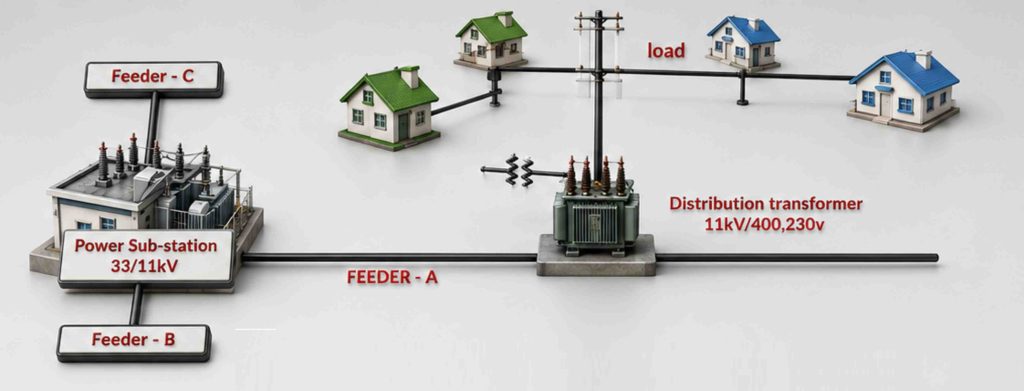
Radial Feeders
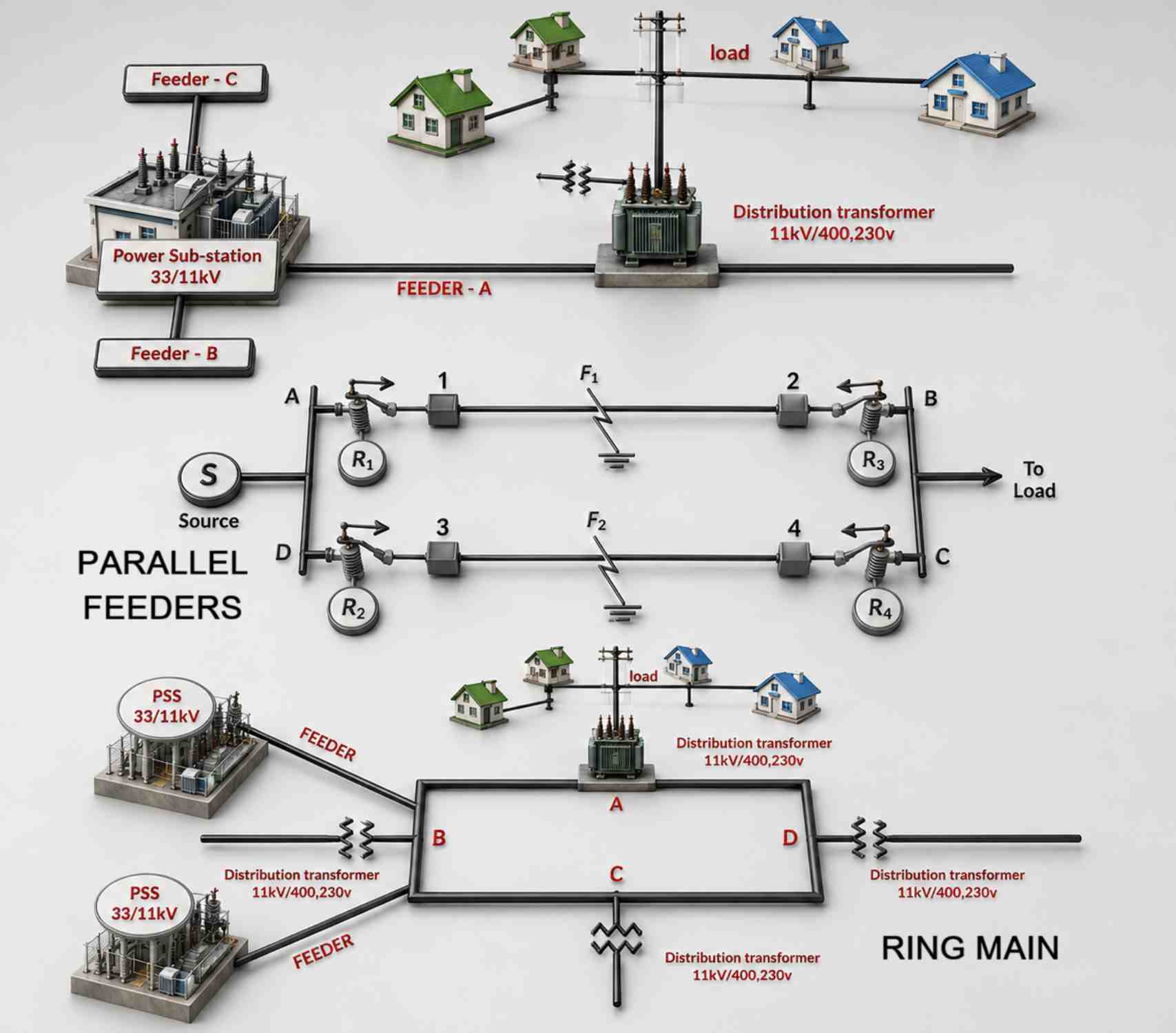
Radial feeders are among the simplest and most commonly used distribution systems. This system is economical and easy to install, making it suitable for areas where the generating station or substation is centrally located near consumers. In a radial feeder system, power flows in only one direction — from the substation to the distributors and finally to consumers. The feeders radiate outward from the power source, similar to the spokes of a wheel.
Advantages of Radial Feeders
- Simple design and operation
- Low installation cost
- Easy maintenance
Disadvantages of Radial Feeders
- Low reliability
- A fault in the feeder can interrupt the power supply to a large number of consumers
Because of these limitations, radial feeders are mainly used in areas where an uninterrupted power supply is not critical.
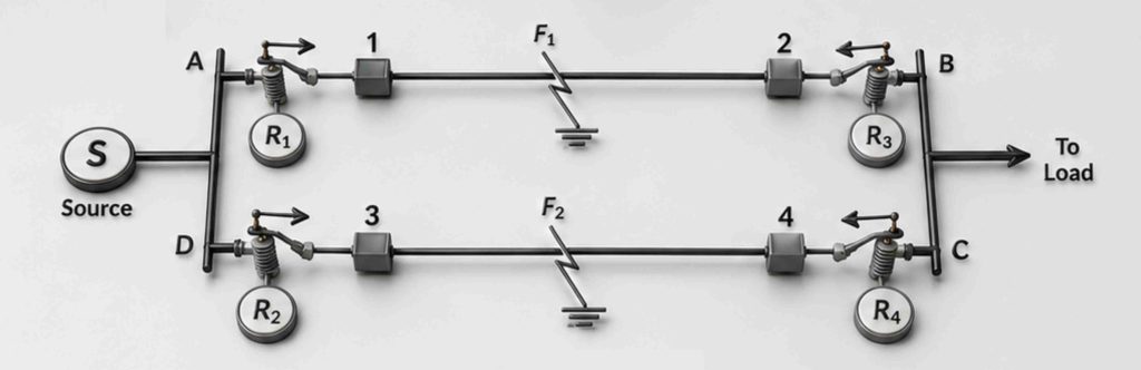
Parallel Feeders
Parallel feeders are used to overcome the reliability issues associated with radial feeders. In this system, two or more feeders are connected in parallel to supply power to the same area. If a fault occurs in one feeder, the other feeder continues supplying electricity, reducing interruptions for consumers. This makes the system more reliable and better suited to transferring heavy electrical loads.
Advantages of Parallel Feeders
- Improved reliability
- Continuous power supply during faults
- Suitable for heavy load transmission
Disadvantages of Parallel Feeders
- Higher installation and maintenance costs
- Increased number of feeders required
Although expensive, parallel feeders are preferred in areas where power continuity is essential.
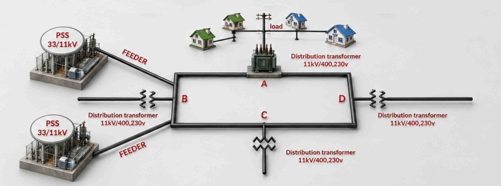
Ring Main Feeders
Ring main feeder systems are widely used in urban and industrial areas because they provide high reliability and operational flexibility. In this system, distribution transformers are connected in a closed loop or ring. The feeder starts and ends at the same substation, creating an alternative path for current flow. If a fault occurs in any section of the ring, that part is isolated using circuit breakers while the remaining network continues to supply power.
Advantages of Ring Main Feeders
- High reliability
- Reduced voltage fluctuations
- Alternative power path during faults
- Continuous supply to consumers
Disadvantages of Ring Main Feeders
- More complex design
- Higher installation cost compared to radial systems
Ring main systems are ideal for densely populated areas where an uninterrupted power supply is important.
Interconnected Systems
Interconnected systems are advanced distribution networks in which ring feeders are energized by more than one generating station or substation. This arrangement provides an even higher level of reliability and efficiency.
In case of a transmission failure or maintenance issue in one section, the system continues to operate using power from another connected source. These systems are commonly used in large-scale power distribution networks.
Advantages of Interconnected Systems
- Very high reliability
- Continuous power supply during failures
- Better load sharing and transmission efficiency
Disadvantages of Interconnected Systems
- Complex network design
- High installation and operational costs
Conclusion
Feeders are an essential part of electrical distribution systems, ensuring efficient power transmission from substations to consumers. Each feeder system has its own advantages and applications. Radial feeders are cost-effective and simple; parallel feeders improve reliability; ring main systems offer uninterrupted supply in urban areas; and interconnected systems provide maximum reliability for large-scale networks. Choosing the right feeder system depends on factors such as load demand, reliability requirements, installation cost, and the nature of the distribution area.