Industrial Electrical Distribution Networks: A System Overview
Electrical distribution networks within industrial facilities constitute critical infrastructure that delivers power reliably from utility-supplied Medium Voltage (MV) feeders to the utilization level for various loads. The following presents a structured analysis of the power flow and the key functional components that comprise this backbone system, typical of factories, processing plants, and other large-scale installations.
Core Components and Their Functional Roles:
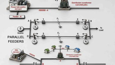
- Ring Main Unit (RMU): A primary node in the MV network, the RMU is a compact, sealed switchgear unit. Its primary function is to ensure a continuous and reliable power supply by facilitating interconnection between multiple incoming MV feeders, typically in a ring configuration. This topology allows for the isolation of faulty sections without disrupting power to downstream loads, thereby enhancing system reliability and availability.
- Step-Down Power Transformers: These transformers perform the essential function of reducing the primary distribution voltage (e.g., 11 kV or 33 kV) to a secondary MV level (e.g., 3.3 kV or 6.6 kV). This intermediate voltage is optimized for the direct supply of high-power Medium Voltage motors, which are standard drivers for large pumps, compressors, and fans in industrial settings.
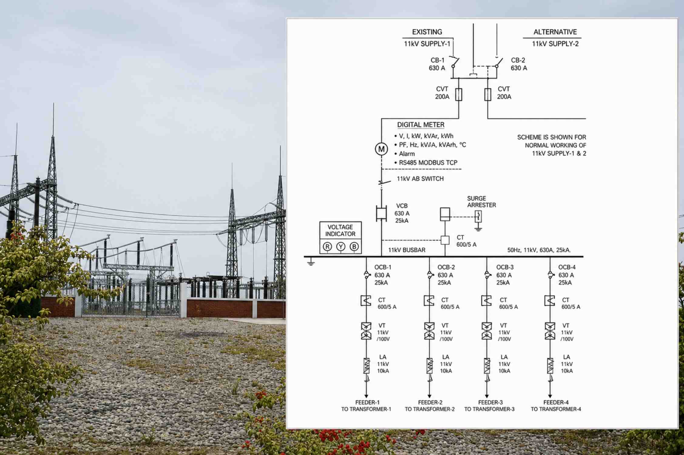
- Medium Voltage (MV) Switchgear: This assembly comprises circuit breakers, disconnect switches, protection relays, and control equipment. It functions as the distribution and protection hub for all MV loads, including the aforementioned MV motors. Its role is to safely switch, control, and isolate circuits while protecting against faults such as overcurrent and short circuits.
- Auxiliary Transformers: Dedicated transformers that further step down the voltage from the MV level (or an intermediate MV bus) to a standardized Low Voltage (LV) level (e.g., 400/230 V). This LV supply is designated for general facility loads, lighting, control systems, and smaller LV motors.
- Main AC Distribution Board (MACDB): Acting as the principal LV distribution point, the MACDB receives power from the auxiliary transformer(s). It houses protective devices and busbars that subdivide and distribute the incoming LV supply to various downstream sections, including Sub-ACDBs (Sub-Distribution Boards) and Motor Control Centers (MCCs).
- Motor Control Center (MCC): An MCC is a centralized, modular assembly of standardized compartments. Each compartment contains combination motor starters, which incorporate contactors, overload relays, and circuit protection for individual motors. The MCC provides a structured and secure environment for the control, protection, and isolation of multiple electric motors from a single location, simplifying operation and maintenance.
Summary of Power Flow:
In summary, industrial power distribution follows a hierarchical architecture: Utility MV power is secured and managed via RMUs; it is then transformed for large drives by Step-Down Transformers and distributed by MV Switchgear. For general LV loads, power is further reduced by Auxiliary Transformers, managed at the Main AC Distribution Board (MACDB), and finally directed to end-use equipment, with motor loads being controlled and protected through dedicated Motor Control Centers (MCCs). This structured approach ensures safety, reliability, and operational efficiency.