Transformer Winding Resistance Measurement: A Comprehensive Guide
Measuring winding resistance is a vital diagnostic procedure for evaluating potential transformer damage caused by issues such as flawed design, assembly errors, improper handling, harsh environments, overloading, or poor maintenance. The main goal of this evaluation is to detect significant variances between windings and find any open circuits. By checking the resistance of transformer windings, technicians can confirm that each circuit is correctly wired and that all electrical connections are securely fastened. Resistance values in transformers may fluctuate due to short-circuited turns, loose joints, or failing contacts within tap changers. Regardless of the specific setup, resistance checks are typically performed phase-to-phase, with the resulting data compared to determine if the unit meets acceptable standards.
1. Introduction and Purpose
Winding resistance measurement is a critical diagnostic procedure used to assess the integrity of transformer windings. This test identifies potential damage resulting from design flaws, assembly errors, improper handling, environmental factors, overloading, or insufficient maintenance.
The primary objectives of this test include:
- Identifying Discontinuities: Detecting open connections or significant differences between windings.
- Verifying Circuit Integrity: Ensuring correct wiring and secure connections within the transformer.
- Detecting Internal Faults: Identifying issues such as shorted turns, loose connections, or deteriorating contacts in tap changers.
2. Measurement Principles
Transformer winding resistance is determined by applying a known DC current through the winding and measuring the resulting voltage drop across its terminals, in accordance with Ohm’s Law. Modern diagnostic equipment typically utilizes a Kelvin bridge (four-wire measurement) to ensure high accuracy by eliminating the resistance of the test leads. These test sets function essentially as high-precision, low-resistance ohmmeters (DLROs) designed for high-inductance loads.
3. Safety Precautions
Due to the high energy and inductance involved, strict safety protocols must be observed:
- Grounding: Ensure all equipment is properly grounded to the local station ground.
- Lockout/Tagout: Treat all high-voltage equipment as energized until verified otherwise through standard lockout/tagout procedures.
- Lead Management: Never remove current or voltage leads while current is flowing. Breaking a DC circuit in an inductive load can generate lethal voltage spikes.
- PPE: Utilize appropriate Personal Protective Equipment (PPE) to mitigate risks from electrical shock and arc flash.
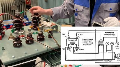
4. Equipment Setup and Connections
Winding resistance testers vary by application, with power transformer units differing significantly from those used for instrument transformers. However, all units include a current source, voltage measurement inputs, and a resistance display.
General Connection Sequence:
- Grounding: Connect the transformer to the station ground, then connect the test set ground.
- Accessories: Attach peripheral devices (e.g., remote controls, warning beacons, or PCs).
- Lead Verification: Connect leads to the test set first and verify all connections are secure before attaching them to the transformer.
- Transformer Attachment: Place voltage leads inside (between) the current leads and the transformer terminals to ensure accurate measurement of the winding itself.
- Power Input: Connect the test set to a power source with a verified low-impedance ground path.
5. Connection Configurations
The following tables outline standard connection configurations for various transformer types.
3-Phase Delta Winding
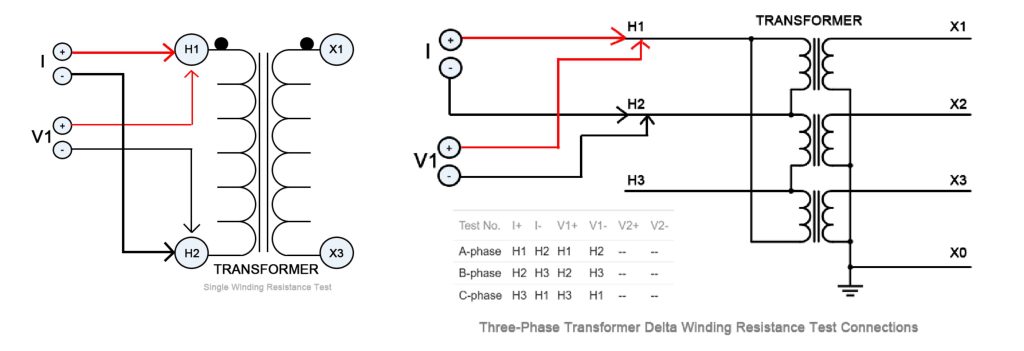
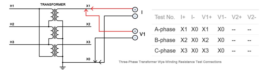
3-Phase Wye Secondary Winding
Dual Winding (Single Phase)
To optimize efficiency, primary and secondary windings can be tested simultaneously.
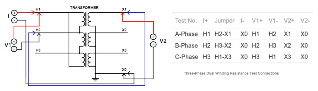
Note: To reduce core saturation time, jumpers should connect windings of opposite polarities. If the resistance difference between windings exceeds a factor of 10, test them separately for better accuracy.
6. Measurement Procedure
Resistance readings must be recorded only after the value has stabilized. Stabilization time varies based on the transformer’s inductance:
- Small Transformers: Seconds.
- Single-Phase HV Transformers: Up to one minute.
- Large/Delta Transformers: Several minutes.
Any fluctuation in the test current will cause a corresponding change in the resistance reading, necessitating a restart of the stabilization period.
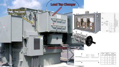
7. Tap Changer Considerations
Each position of a tap changer must be verified, as the mechanical movement can introduce contact issues.
- Off-Load Taps: The transformer must be fully discharged before changing tap positions.
- On-Load Tap Changers (OLTC): These may be operated while the test set is active, thereby verifying the “make-before-break” functionality.
- Routine Maintenance: If time is limited, testing at the designated operating tap is acceptable.
8. Interpretation of Results
Results are typically evaluated by comparing the resistance of adjacent windings at the same tap position.
- Acceptance Criteria: Readings within 1% of each other are generally considered acceptable.
- Historical Comparison: Field results can be compared to factory data, though field conditions (environment and temperature) will differ from controlled factory settings.
Temperature Correction
Resistance is temperature-dependent and must be corrected to a standard reference (usually 75°C or 85°C) for accurate trending.
RC = RM x {(CF + CT )/(CF + WT)}
| Variable | Description |
| RC | Corrected Resistance |
| RM | Measured Resistance |
| CF | Correction Factor (Copper: 234.5; Aluminum: 225) |
| CT | Reference Temperature (75°C or 85°C) |
| WT | Winding Temperature at time of test |
If a temperature gauge is unavailable, use the oil temperature or the ambient air temperature (for dry-type transformers).
9. Post-Test Demagnetization
After completing resistance tests, the transformer core must be demagnetized to remove residual flux caused by the DC test current. Failure to demagnetize can result in high inrush currents that may trip protective relays upon energization. Demagnetization is achieved by applying multiple cycles of alternating DC at decreasing current levels. This process only needs to be performed on a single winding after all resistance measurements are finalized.