The Transformer Turns Ratio (TTR): Principles, Calculation, and Testing
Introduction to Transformer Operation
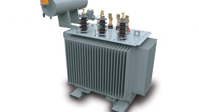
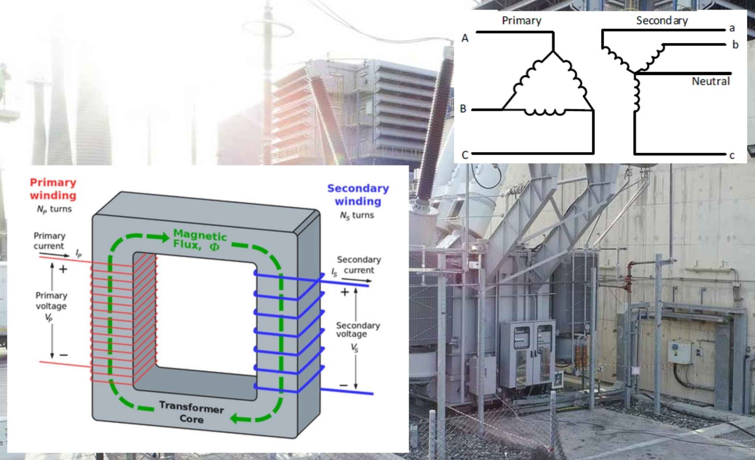
A transformer is a static electrical device that efficiently transfers electrical energy between two or more circuits through electromagnetic induction. Each phase of a transformer typically consists of two separate coil windings—the primary and the secondary—wound around a common magnetic core. The primary winding is connected to the power source. When an alternating current (AC) energizes this winding, it generates an alternating magnetic field, or flux, which circulates through the core. This flux then links with the secondary winding, inducing a voltage across it.
Defining the Transformer Turns Ratio (TTR)
The Transformer Turns Ratio (TTR) is a fundamental parameter defined by the ratio of the number of turns in the primary winding (N1) to the number of turns in the secondary winding (N2). Crucially, the voltage induced per turn in the secondary winding is equal to the voltage per turn in the primary winding. This principle dictates the relationship between the turns ratio and the voltage ratio.
Step-Up and Step-Down Classification
The TTR determines whether a transformer is classified as step-up or step-down:
- Step-Down Transformer: If the secondary winding has fewer turns than the primary (N2 < N1), the induced secondary voltage (E2) will be lower than the primary voltage (E1).
- Step-Up Transformer: If the secondary winding has more turns than the primary (N2 > N1), the induced secondary voltage (E2) will be higher than the primary voltage (E1).
Note on Winding Designation: The primary winding is always connected to the source, and the secondary winding is connected to the load. Either the high-voltage (HV) or low-voltage (LV) winding can serve as the primary or secondary, depending on the application.
Mathematical Formulation of TTR
For an ideal transformer, the ratio of voltages is directly proportional to the ratio of turns, and inversely proportional to the ratio of currents. This relationship is derived from the principle of conservation of apparent power (Volt-Amps), which states that the power in the primary circuit equals that in the secondary circuit (neglecting losses). The following equation expresses the core relationship:
E1/E2 = N1/N2 = I2/I1
| Variable | Description | Unit |
| E1 | Primary Winding Voltage | Volts (V) |
| E2 | Secondary Winding Voltage | Volts (V) |
| N1 | Number of Turns in Primary Winding | Turns |
| N2 | Number of Turns in Secondary Winding | Turns |
| I1 | Primary Winding Current | Amperes (A) |
| I2 | Secondary Winding Current | Amperes (A) |
This formula demonstrates that if the voltage is stepped up, the current must be stepped down proportionally, and vice versa, to maintain constant apparent power. This ratio remains constant unless the transformer is equipped with a tap changer.
Calculation Examples
Example 1: Calculating Secondary Voltage
Given a primary voltage (E1) of 110 V, a primary turns count (N1) of 100, and a secondary turns count (N2) of 400, the secondary voltage (E2) is calculated as follows:
E1/E2 = N1/N2
110 / E2 = 100 / 400 → E2 = 440 Volts
Example 2: Calculating Secondary Current
Using the results from Example 1 and a primary current (I1) of 20 A, the secondary current (I2) is calculated using the inverse relationship:
E2 x I2 = E1 x I1
440 x I2 = 110 x 20 → I2 = 5 amps
In this case, the turns ratio (N1/N2) is 100/400 = 1:4 The voltage ratio (E1/E2) is 110/440 = 1:4 The current ratio (I1/I2) is 20/5 = 4:1
Three-Phase Wye Connection Consideration
For three-phase transformers with a Wye (Y) connection, the TTR is often calculated based on the line-to-neutral voltage of the Wye winding. To obtain the correct line-to-neutral voltage from the line-to-line voltage, the latter must be divided by sqrt{3} (approximately 1.732). For a transformer rated 13200 V (line-to-line) on the primary and 480Y/277 V on the secondary, the TTR is calculated using the line-to-line primary voltage and the line-to-neutral secondary voltage:
Plain Text
TTR = 13200-480Y/277 would be 13200/277 = 47.653
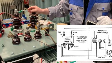
Transformer Turns Ratio Testing
The Transformer Turns Ratio (TTR) test is a critical diagnostic procedure used to verify the integrity of a transformer’s windings and to detect potential issues such as shorted turns, which are indicative of insulation failure.
Test Procedure
- Preparation: The position of the tap changer must be confirmed and set to the nameplate voltage base. Failure to do so will invalidate the comparison with the nameplate data.
- Measurement: A known, low AC voltage is applied across one winding (typically the high-voltage winding to reduce induced voltage hazards). The resulting induced voltage is then measured on the corresponding secondary winding.
- Comparison: The voltage ratio obtained from the field test is compared against the theoretical ratio specified on the transformer’s nameplate. The nameplate’s phasor diagram must be consulted to ensure that the correct primary and secondary windings are being compared.
Acceptance Criteria
The measured TTR should fall within a tolerance of 0.5% of the nameplate ratio, or the specific tolerance defined by the manufacturer. New, high-quality transformers typically exhibit a measured ratio within 0.1% of the nameplate value. For three-phase transformers with Delta/Wye or Wye/Delta connections, a three-phase equivalency test is often performed, with calculations conducted across corresponding single windings.