Voltage Regulation in Power Transformers: A Technical Review of Tap Changer Technologies and Maintenance Practices
Abstract
Power system stability and efficiency necessitate continuous voltage regulation to accommodate dynamic load conditions. This paper provides a technical review of the mechanisms used to adjust voltage in power transformers, focusing on the design, operational constraints, and maintenance of both De-Energized Tap Changers (DETC) and On-Load Tap Changers (OLTC). The operational requirement for system isolation in DETC is contrasted with the continuous regulation capability of OLTCs. Furthermore, the critical role of diagnostic testing, including exciting current and dynamic winding-resistance measurements, in mitigating the high failure rate of these electromechanical components is discussed.
The fundamental characteristic of electrical energy is that its generation rate must precisely match the system’s instantaneous demand. Consequently, power transformers, essential components of the electrical grid, must regulate their output voltage to maintain system stability under varying load conditions.
2. Transformer Principles and Voltage Adjustment
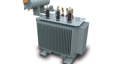
Transformers facilitate the efficient transfer of electrical energy between circuits via the principle of magnetic induction. Each phase winding comprises a primary and a secondary coil wound around a common magnetic core. The output voltage of a transformer is directly proportional to the ratio of the number of turns in the primary and secondary windings, as well as the input voltage. Therefore, voltage adjustment can be achieved through two primary methods: modifying the input voltage or altering the effective number of winding turns. Tap changer mechanisms provide an external, controllable means to execute this turn-ratio adjustment.
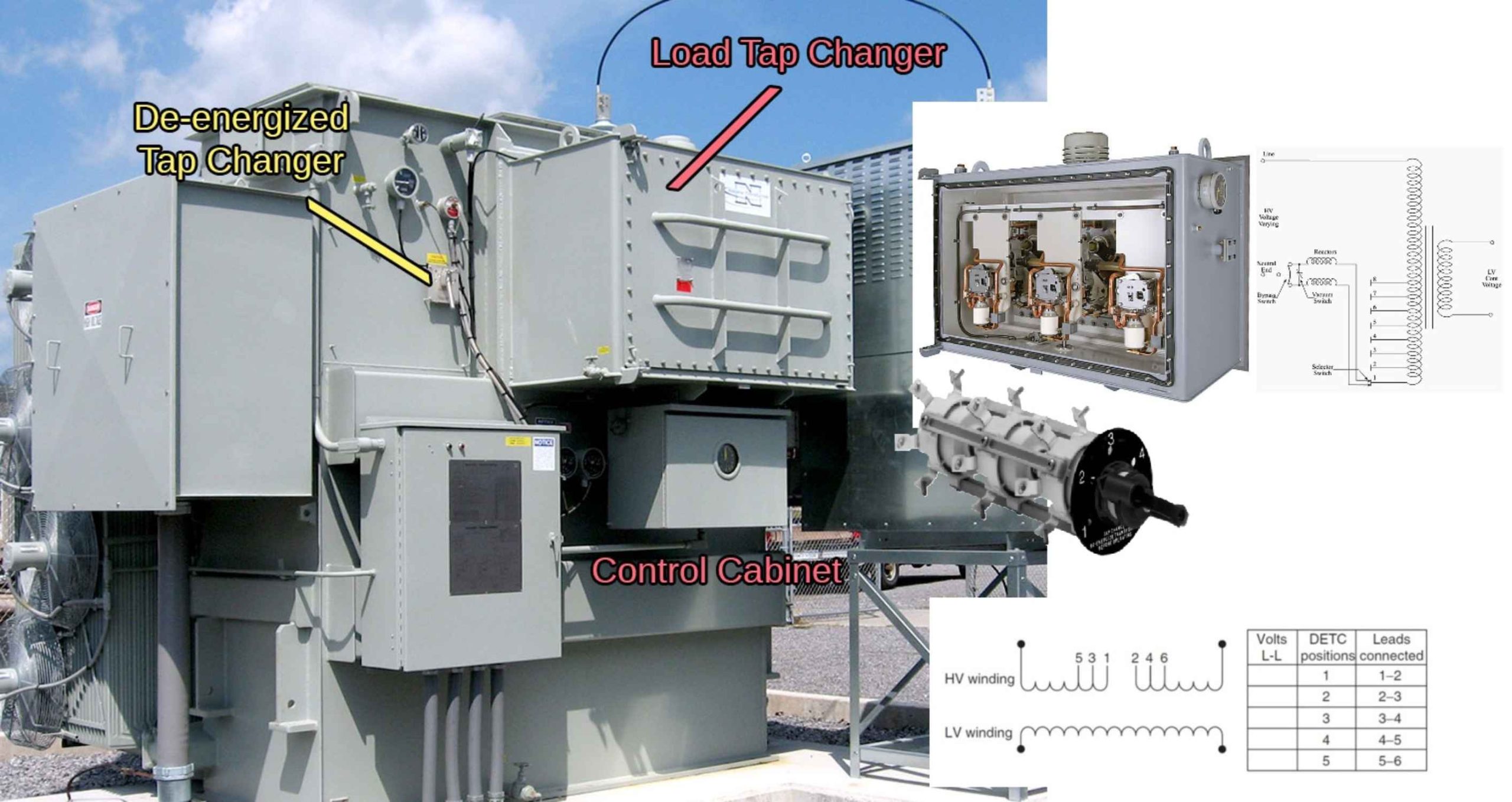
3. De-Energized Tap Changers (DETC)
The De-Energized Tap Changer (DETC), also referred to as an off-load tap changer, is a standard feature on many power transformers. This device is typically mounted on the high-voltage winding and allows for the adjustment of the winding turns.
A critical operational constraint of the DETC is that adjustments can only be performed when the transformer windings are completely isolated and de-energized. This limitation arises because the switch is neither designed nor rated to interrupt high-voltage electrical loads. Consequently, DETC adjustments are generally reserved for infrequent, long-term system changes, such as seasonal variations, and necessitate a planned electrical outage. The DETC is commonly configured with a fixed number of positions (e.g., five: A, B, C, D, E, or 1 through 5). Furthermore, a lack of regular operation can increase the risk of contact failure when the switch is eventually moved.
4. On-Load Tap Changers (OLTC)
To accommodate the dynamic and continuous fluctuations inherent in power system operation, a more sophisticated voltage regulation mechanism is required. The On-Load Tap Changer (OLTC), also known as a Load Tap Changer (LTC), is engineered to perform multiple position changes daily to compensate for load shifts without interrupting the nominal power supply. OLTCs can be integrated internally within the main transformer tank or housed in a separate, sealed, liquid-filled compartment. The latter configuration uses feed-through tap connections on the transformer’s rear panel.
4.1. OLTC Classification and Operation
OLTCs are broadly classified into mechanical, electronically assisted, or fully electronic types. The control circuitry monitors the system and initiates a tap change operation (raise or lower) to maintain the desired output voltage. The selector switches within the mechanism facilitate the physical change in tap position on the regulating windings, but they are not responsible for interrupting the circuit load current.
The operational sequence for most OLTCs is motor-driven, although manual operation can be employed in the event of motor failure. The sequence is mechanically interlocked to ensure the correct order of contact operation, as any failure in the mechanism can result in severe damage to the transformer and the tap changer itself.
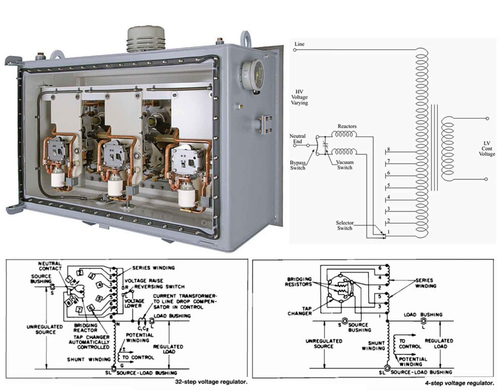
A standard OLTC, such as a 32-step unit, typically comprises 16 raise positions and 16 lower positions. The physical taps are situated on a regulating winding within the main transformer tank, which is connected in series with the primary winding via a reversing switch. Voltage is regulated by a “stepping” action of movable contacts, which add or subtract turns on the regulating winding. The polarity of the connection through the reversing switch determines whether the voltage is raised or lowered. The neutral position is the condition in which the OLTC is neither raising nor lowering voltage, and it is the only position in which the reversing switch does not carry current.
4.2. Load Current Interruption Mechanisms
Since the load current must not be interrupted during a tap change, an interval exists where two voltage taps are momentarily spanned. This bridging action is managed by a diverter switch, which temporarily inserts a high impedance in series with the short-circuited turns to prevent high circulating currents.
OLTCs utilize different mechanisms to manage the transition:
| OLTC Type | Transition Mechanism | Key Characteristic |
| Mechanical | Multiple tap selector switches | Makes the new connection before releasing the previous one; uses an impedance-diverting switch. |
| High-Speed Resistive | Resistor pair | Utilizes a resistor pair to absorb energy; transition must be executed swiftly to prevent overheating; bridging position is not a service position. |
| Reactance Type | Preventive Autotransformer (PA) | Uses a dedicated preventive autotransformer winding as the diverter impedance; the PA acts as a current-limiting device during the bridging tap position. |
The Preventive Autotransformer (PA), also known as a bridging reactor, is employed to increase the impedance of the selector circuit and limit the magnitude of circulating current induced by the voltage difference between the two spanned taps.
5. Diagnostic Testing and Maintenance
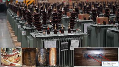
Tap changers have historically been identified as a leading cause of power transformer failures. Faults in OLTCs are generally categorized as:
- Dielectric Failures: Related to the quality of the insulating oil or insulation breakdown.
- Thermal Failures: Caused by poor terminations or excessive heating.
- Mechanical Failures: Including contact wear, misalignment, sheared linkage, and lubrication issues.
Routine inspection and maintenance are essential for mitigating premature failure. Analysis of the tap changer insulating fluid can effectively detect overheating and excessive arcing without requiring internal inspection.
Electrical diagnostic tests complement oil analysis and can identify problems not detectable solely through fluid testing.
| Diagnostic Test | Application | Detectable Issues |
| Exciting Current Test | Both DETC and OLTC | Mechanical issues such as misalignment, contact wear, loose connections, and open/short-circuited turns. |
| DC Winding Resistance | Current-carrying path | Loose electrical connections and partial open-circuited conditions; involves applying a known DC current and measuring voltage drop. |
| Dynamic Winding Resistance | OLTC diverter circuit | Potential problems with the diverter circuit or transition resistors; measures DC current and resistance as a function of time during tap change operation. |
| Turns Ratio Check | Main transformer windings | Verifies the turns ratio at each tap position. |
| Sweep Frequency Response Analysis (SFRA) | Mechanical integrity | Assesses the mechanical integrity of the tap windings and their leads (mid- to upper-frequency ranges). |
Given that tap changers are electromechanical devices, it is recommended that an oil sample be taken annually and that comprehensive electrical testing be performed at least biannually. The frequency of inspection and testing should be adjusted based on the equipment’s environmental and physical conditions and the transformer’s criticality within the overall power system.