Transformer Polarity: Principles and Testing Procedures

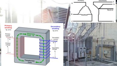
Transformer polarity is a critical design characteristic that dictates the relative direction of the induced voltage between the primary and secondary windings. Understanding and verifying polarity is essential for several operational requirements, including paralleling transformers to increase capacity and connecting multiple single-phase transformers to form a three-phase bank. Furthermore, the correct polarity is vital when connecting current transformers for accurate relay protection and metering applications.
Fundamentals of Transformer Polarity
Two factors fundamentally determine the polarity of a transformer:
- The direction of the coil windings around the core (i.e., clockwise or counterclockwise).
- The configuration of the external lead connections.
Polarity marks, typically represented by a dot or a plus/minus sign on both the transformer casing and its nameplate, indicate the terminals where the input and output voltages share the same instantaneous polarity. This means that at any given moment, the voltage entering the marked primary terminal will induce a voltage that exits the marked secondary terminal in the same relative direction.
Polarity Testing Procedure (Reduced Voltage Method)
The most common and reliable method for determining transformer polarity is the reduced voltage test, which utilizes a voltmeter to compare the applied voltage with the resultant voltage across the combined windings.
Safety Precaution
DANGER: Always use the lowest possible AC voltage source to energize the winding. An adjustable AC voltage source is highly recommended to minimize potential hazards during the test procedure.
Test Steps
- Preparation: Ensure the transformer is de-energized and isolated.
- Jumper Connection: Connect a temporary jumper wire between the H1 terminal (high-voltage side) and the X1 terminal (low-voltage side).
- Voltmeter Setup: Connect an AC voltmeter between the H2 terminal and the X2 terminal.
- Voltage Application: Apply a reduced AC voltage (e.g., 120V or less) across the H1 and H2 terminals.
- Measurement: Record the voltage reading displayed on the voltmeter.
Polarity Determination
The measured voltage determines the transformer’s polarity, as summarized in the table below:
| Polarity Type | Voltmeter Reading (Vmeasured) | Relationship to Applied Voltage (Vapplied) | Typical Application |
| Additive | Vmeasured = Vapplied + Vsecondary | The measured voltage equals the sum of the high-voltage applied and the induced low-voltage winding. | Small distribution transformers |
| Subtractive | Vmeasured < Vapplied | The measured voltage is less than the applied voltage. | Larger power transformers |
Note: $V_{\text{secondary}}$ is the voltage across the secondary winding (X1-X2) when $V_{\text{applied}}$ is across the primary (H1-H2).
ANSI Rule of Thumb for Single-Phase Transformers
The American National Standards Institute (ANSI) provides a visual rule of thumb for determining the polarity of single-phase transformers based on terminal arrangement . This rule applies when the observer is facing the low-voltage side of the transformer (the side marked X1, X2).
| Terminal Arrangement | Polarity Type |
| The H1 terminal is always on the far left. | |
| The X1 terminal is also on the left. | Subtractive Polarity |
| The X1 terminal is on the right. | Additive Polarity |
Three-Phase Transformer Bushing Arrangement
For three-phase transformers, the terms “additive polarity” and “subtractive polarity” are not applicable. Instead, ANSI standards govern the standardized arrangement of bushings to ensure consistent connections.
The arrangement is determined by facing the transformer:
| Side | Bushing Arrangement (Left to Right) |
| High-Voltage Side | H3, H2, H1, and H0 (Neutral) |
| Low-Voltage Side | X0 (Neutral), X1, X2, and X3 |