Analysis of Acoustic Noise Generation and Mitigation in Power Transformers
All power transformers exhibit an inherent acoustic noise level, which is fundamentally determined by the design, size, and construction of the core and coil assembly. The measured sound level at an installation site can vary significantly from factory test conditions due to operational factors. Transformer noise is a complex phenomenon resulting from the superposition of several distinct sources, primarily categorized as core sound, load sound, auxiliary equipment noise, and environmental factors.
1. Core Sound: The Role of Magnetostriction
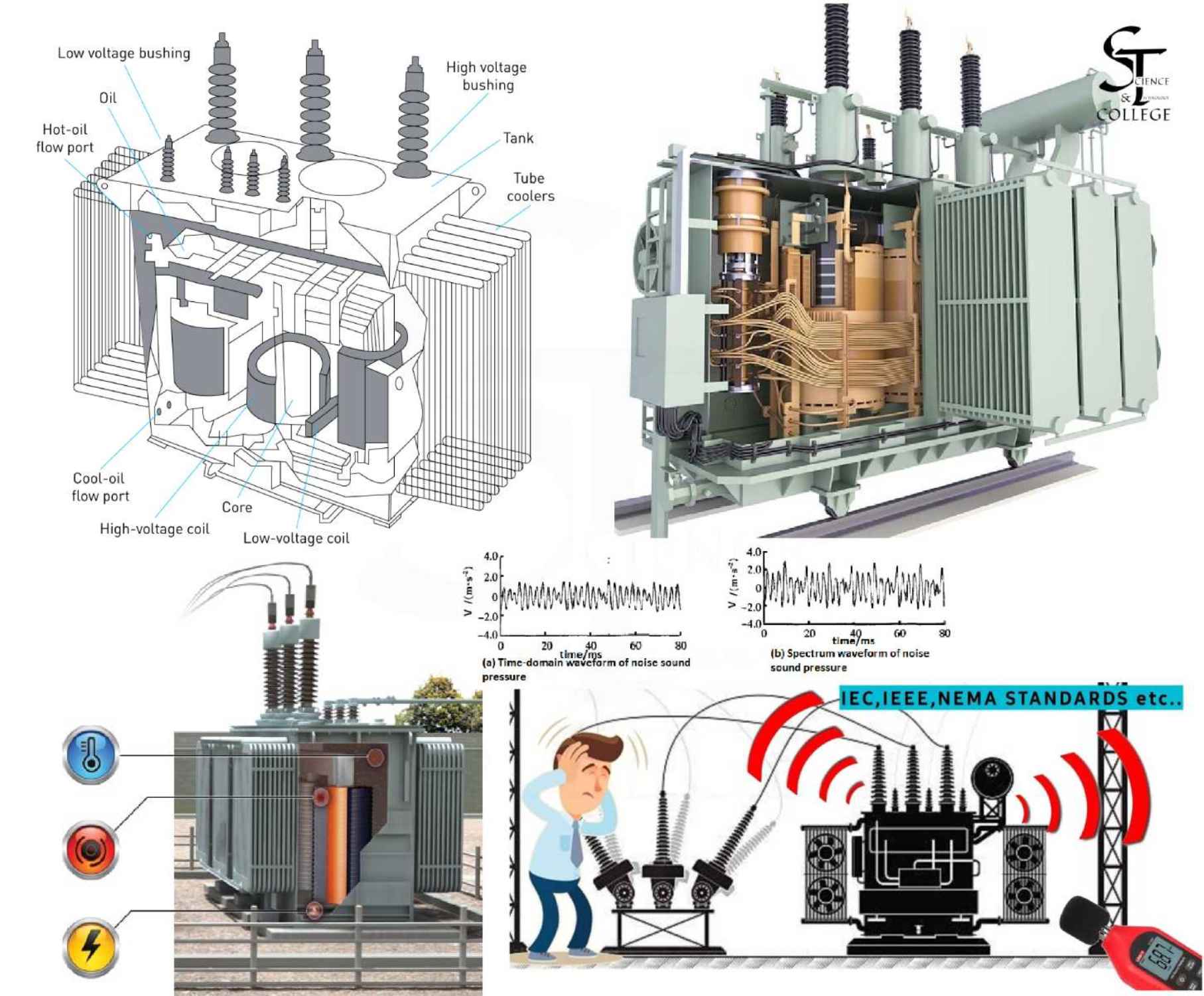
The primary source of transformer sound is the core, a phenomenon driven by magnetostriction. Magnetostriction is the property of ferromagnetic materials, such as the iron used in transformer laminations, to change their physical dimensions when subjected to a magnetic field. This dimensional change is typically on the order of a few parts per million.
Transformer cores are constructed from stacked, thin iron laminations separated by a non-conducting insulating layer. When the core is excited by an alternating voltage and current, the magnetic field causes the laminations to extend and contract. Since the change in dimension is independent of the magnetic flux direction, this physical deformation occurs twice per full cycle of magnetization, resulting in a vibration frequency that is double the line frequency.
Aging and Operational Factors: Over time, the adhesive and insulation binding the laminated layers can degrade, leading to slight separation. This mechanical loosening allows the layers to vibrate with greater amplitude, which is perceived as an increase in the humming noise. Factors influencing the magnitude and frequency components of core sound include flux density, core material, core geometry, and the waveform of the excitation voltage. Due to the non-linear nature of the magnetostriction curve, higher-order even harmonics are also generated in the resulting core vibration, particularly at higher induction levels. The low-frequency, tonal nature of core noise makes it particularly challenging to attenuate, as low frequencies propagate farther with less absorption than higher-frequency noise from other sources.
2. Load Sound and Harmonic Effects
Load noise is predominantly produced by the axial and radial vibration of the windings, which is caused by electromagnetic forces proportional to the square of the load currents. Vibrations in the transformer tank walls and magnetic shields, also induced by load currents, can contribute to the overall load noise.
The fundamental frequency of load noise is typically twice the power frequency. However, the presence of current and voltage harmonics, common in applications like rectifier transformers, can produce vibrations at twice the harmonic frequencies. This can lead to a substantial increase in the overall sound level. Furthermore, harmonic content in the load current can interact with the power frequency load current, resulting in a larger impact on the sound level than might be expected from the amplitude of the harmonic currents alone. This effect is a major contributor to increased sound levels in HVDC and rectifier transformers. Nonlinear loads can also introduce harmonics into the excitation voltage, thereby influencing and increasing the core sound levels.
3. Auxiliary and Structural Noise Sources
Noise generated by auxiliary equipment and structural elements also contributes to the total acoustic output of a transformer.
•Cooling System Noise: The primary source of heat generation is copper loss in the windings and core ($I^2R$ losses). This heat is often dissipated by cooling fans and pumps. Noise produced by cooling fans is a more significant contributor to the total noise in smaller-rated transformers and those with low induction levels. Factors affecting fan noise include tip speed, blade design, number of fans, and radiator arrangement. Cooling equipment noise typically dominates the very low and very high-frequency ends of the sound spectrum, while core noise dominates the intermediate range (e.g., 100 Hz to 600 Hz).
•Mechanical and Structural Resonance: The mechanical resonance of the transformer mounting structure, core, and tank walls can significantly amplify vibrations and the resulting acoustic noise. Poorly designed or marginally specified magnetic shielding can also become a notable source of sound.
4. Effects of DC Magnetization
Even a moderate level of DC magnetization in a transformer core can result in a significant increase in the audible sound level. DC magnetization not only increases the power level of the normal even harmonics of the power frequencies but also introduces odd harmonic tones to the overall sound spectrum.
Modern cores often possess a high remnant flux density. Consequently, upon initial energization, the core sound levels may temporarily exceed the factory test value by as much as 20 dB. It is therefore recommended that a transformer be energized for approximately six hours before its sound levels are formally evaluated. Historically, DC feeders for transportation systems were a source of DC fields; however, the increased use of power electronic equipment in power transmission and industry has expanded the number of potential sources for DC magnetization. Geomagnetic storms can also induce severe DC magnetization in transformers connected to long transmission lines.
5. Acoustical Environment and Resonance
The final perceived sound level is heavily influenced by the installation environment. Sound propagation is affected by atmospheric absorption, intervening barriers, and reflective surfaces. Sound waves can be amplified through reflection and radiation via walls, floors, ceilings, and mechanical vibrations transmitted through air ducts, conduits, and mounting bases.
Dry-type transformers are frequently installed inside buildings. In rooms with a low sound absorption coefficient, sound waves will reflect repeatedly, leading to a build-up of the sound level within the space. For expected sound levels of dry-type transformers, reference should be made to industry standards such as NEMA ST-20 and ANSI C89.2 .
6. Noise Mitigation Strategies
When transformers must be located in noise-sensitive areas, specific precautions should be implemented to prevent the amplification of transformer sound:
| Category | Mitigation Strategy | Rationale |
| Vibration Isolation | Loosen anchor bolts between the transformer and enclosure, allowing the unit to rest solely on vibration pads (excluding certified seismic units). | Minimizes the transmission of mechanical vibration to the surrounding structure. |
| Use flexible conduit and bus connections. | Prevents the rigid transfer of vibration through electrical and mechanical connections. | |
| Structural Placement | Avoid mounting transformers on walls, balconies, and floors with low mass. | Low-mass structures are more susceptible to resonant vibration and sound radiation. |
| Ensure mounting surfaces are even and stable. | Prevents uneven stress distribution that can exacerbate internal vibrations. | |
| Acoustic Treatment | Install transformers in locations where the noise will be least objectionable, avoiding corners, hallways, and stairways. | Corners and confined spaces act as acoustic amplifiers. |
| Avoid rooms where hard, reflective surfaces are in close proximity to the transformer. | Reduces sound reflection and the resulting build-up of sound level. | |
| Utilize acoustic absorbing materials on walls, floors, and ceilings. | Increases the sound absorption coefficient of the room, reducing reverberation. | |
| Clearance | To meet NEMA-listed average sound levels, a transformer should ideally be installed with a 10-foot clearance on all sides (excluding the floor or ground). | Units located in close proximity to hard surfaces may produce higher than average sound levels due to close-range reflection. |
References
[1] NEMA ST-20: Dry-Type Transformer Sound Levels.
[2] ANSI C89.2: American National Standard for Dry-Type Transformers.