The Thermal Endurance of Transformers: A Comprehensive Guide to Insulation Classes
The insulation system is arguably the most critical component in a transformer, as its thermal endurance directly determines the unit’s operational lifespan, reliability, and safety. Insulation classes are a standardized measure of this endurance, defining the maximum temperature an insulation system can safely withstand over its expected lifetime. Understanding these classifications is essential for engineers and operators to ensure transformers are specified and operated within safe thermal limits, thereby maximizing their service life.
The Components of Maximum Winding Temperature
A transformer’s maximum allowable temperature is not a single value but a composite of three primary thermal factors. The insulation class defines the Maximum Winding Temperature—the absolute thermal limit—which is the sum of the ambient temperature, the average winding temperature rise, and the hot-spot allowance.
The calculation for the maximum temperature is expressed as:
Tmax = Tambient + ΔTavg + ΔThotspot
Where:
- Tmax is the Maximum Winding Temperature (the insulation class rating).
- Tambient is the Ambient Temperature (the temperature of the surrounding cooling medium, typically air).
- ΔTavg is the Average Winding Temperature Rise (the average temperature increase of the windings above the ambient temperature, caused by load losses).
- ΔThotspot is the Hot Spot Temperature Rise (the allowance for the hottest point in the winding, which is always higher than the average winding temperature).
The maximum acceptable temperature rise values are typically based on a standard ambient temperature of 30 °C over any 24 hours, with a maximum ambient temperature of 40 °C at any time. This standardization ensures a consistent baseline for thermal design and performance evaluation.
Detailed Analysis of Transformer Insulation Classes
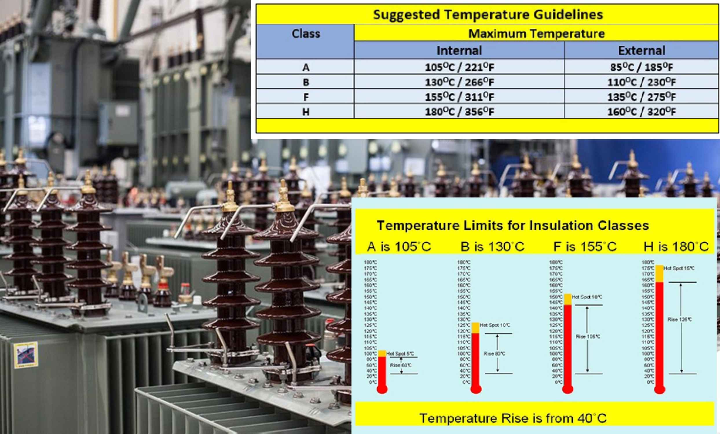
The following table, based on industry standards, summarizes the relationship between the Insulation Rating, the corresponding Insulation Class letter, and the critical temperature limits. These classes are defined by the thermal endurance of the materials used in the winding insulation, core barriers, and impregnation systems.
| Insulation Rating | Insulation Class | Average Winding Temperature Rise | Hot Spot Temperature Rise | Maximum Winding Temperature |
| Class 105 | A | 55 °C | 65 °C | 105 °C |
| Class 150 or 130 | B | 80 °C | 110 °C | 150 °C |
| Class 180 | F | 115 °C | 145 °C | 180 °C |
| Class 200 | N | 130 °C | 160 °C | 200 °C |
| Class 220 | H | 150 °C | 180 °C | 220 °C |
Interpretation of Key Thermal Parameters
- Insulation Rating and Class: These are the thermal limits of the insulation material itself. For instance, a Class 220 (H) insulation system is designed to maintain its electrical and mechanical integrity up to 220 °C.
- Average Winding Temperature Rise: This value represents the bulk temperature increase of the winding. It is measured using the change-in-resistance method and is a key indicator of the transformer’s overall thermal performance and efficiency.
- Hot Spot Temperature Rise: This is the most critical parameter for insulation life. The hot spot is the point within the winding that experiences the highest temperature, typically due to localized heating and reduced cooling flow. The hot spot temperature rise is the difference between the maximum winding temperature and the average winding temperature, accounting for the non-uniform heat distribution. For example, in a Class 220 (H) system, the hot spot temperature rise is 180 °C. When combined with the standard 40 °C maximum ambient, this results in the 220 °C maximum winding temperature.
The Exponential Relationship Between Temperature and Lifespan
The primary reason for defining and adhering to these thermal limits is the exponential relationship between operating temperature and the degradation rate of the insulation material. This relationship is often summarized by the “10-Degree Rule” (or Arrhenius Law for chemical reactions), which states that for every 10 °C increase in operating temperature above the rated insulation temperature, the expected insulation life is approximately halved.
Conversely, operating a transformer with a higher insulation class but a lower designed temperature rise significantly extends its service life. This approach provides a crucial thermal headroom that allows the transformer to tolerate temporary temperature excursions caused by real-world operating stresses, such as:
- High Ambient Temperatures: Installations in confined spaces or industrial environments may experience sustained ambient temperatures above the standard 30 °C average.
- Harmonic Distortion: Non-linear loads introduce harmonic currents that increase stray losses, leading to additional, unplanned temperature rise.
- Overload Conditions: Short-term overloads or cyclic duty can push the winding temperatures beyond the nameplate rating.
By selecting a higher insulation class (e.g., Class 220) and designing for a lower temperature rise (e.g., 115 °C instead of 150 °C), the transformer operates at a lower temperature, preserving the insulation’s chemical structure and ensuring a much longer, more reliable service life.
Conclusion
Transformer insulation classes are more than just a set of numbers; they are the foundation of a transformer’s long-term reliability. By standardizing the maximum allowable temperature, the average winding temperature rise, and the hot spot allowance, these classes provide a clear framework for thermal design. Adherence to these limits, coupled with an understanding of the exponential impact of temperature on insulation life, is paramount for maximizing the performance and longevity of any transformer installation.