Technical Report: The Pillars of Grid Management – CTs, PTs, and Capacitor Banks
Introduction: The Architecture of a Modern Grid
The reliable operation of a modern electrical power system hinges on a complex interplay of high-voltage apparatus and precision sensing and control equipment. The core challenge in managing high-voltage, high-current networks is safely and accurately measuring and controlling these vast quantities of power. This is achieved through specialized components that serve as the eyes and ears of the grid: Current Transformers (CTs) and Potential Transformers (PTs). Furthermore, maintaining the quality and stability of the power supply requires dynamic reactive power management, a function primarily fulfilled by Capacitor Banks. All these elements are unified and represented within the critical document known as the Single Line Diagram (SLD).
The Single Line Diagram (SLD): The Grid’s Blueprint
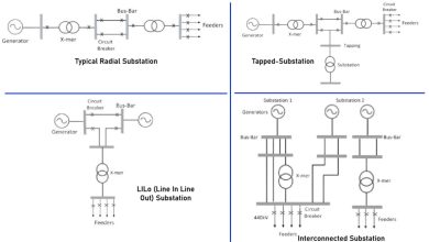
The Single Line Diagram is arguably the most fundamental document in electrical engineering, serving as the schematic representation of a three-phase power system using simplified, single-line notation. It is not merely a drawing; it is the primary tool for system safety, maintenance planning, and fault analysis.
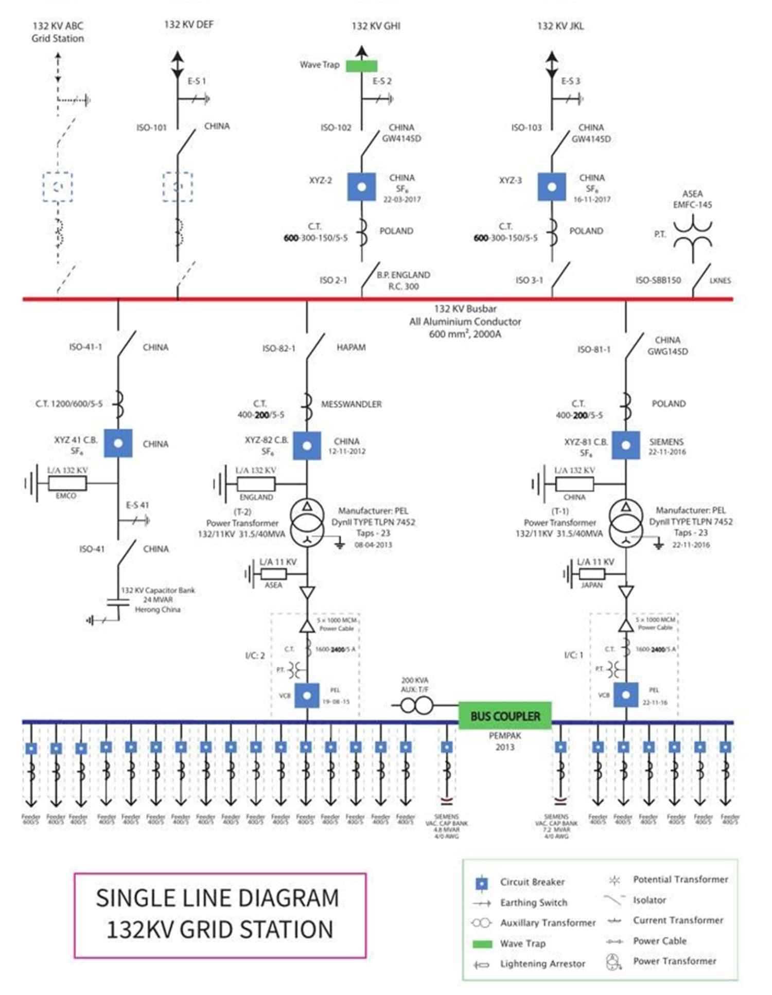
The SLD provides a high-level overview of how power is generated, transmitted, and distributed, detailing the major components, including generators, transformers, circuit breakers, and busbars. Critically, it also indicates the location and connection of the instrument transformers and protective devices.
| SLD Role | Description |
| Safety and Compliance | Clearly identifies isolation points, grounding locations, and the sequence of protective devices, which is vital for safe switching and lockout/tagout procedures. |
| Maintenance Planning | Facilitates troubleshooting and preventive maintenance by providing a clear, logical flow of the system, allowing engineers to quickly locate equipment and understand its context. |
| System Analysis | Serves as the foundation for complex engineering studies, including short-circuit current calculations, selective coordination, and load flow analysis. Without an accurate SLD, managing a modern grid would be like navigating a city without a map. |
Instrument Transformers: The Eyes and Ears of the Grid
Instrument Transformers (ITs) are essential for scaling down the primary system’s high currents and voltages to standardized, low-level secondary values that can be safely handled by meters, relays, and control equipment. They provide both an accurate proportional representation of the primary quantity and crucial electrical isolation.
Current Transformers (CTs)
A Current Transformer is designed to step down high primary currents to a standardized secondary current, typically 5 A or 1 A.
- Function and Connection: The CT’s primary winding consists of very few turns (often a single conductor or busbar) and is connected in series with the line carrying the current to be measured. It operates as a step-up transformer in terms of voltage to achieve the current step-down, following the inverse relationship of turns ratio: Iprimary / Isecondary = Nprimary / Nsecondary
- Applications: CTs are indispensable for metering (e.g., utility billing, load profiling) and protection (e.g., overcurrent, differential, and distance protection relays).
- Critical Safety Rule: The secondary circuit of a CT must never be open-circuited while the primary is energized. An open secondary can cause the core to saturate, inducing dangerously high voltages that risk insulation failure, arcing, or even explosion. Unused CT secondaries must always be short-circuited or connected to a burden.
Potential Transformers (PTs)
A Potential Transformer (also known as a Voltage Transformer or VT) is a precision step-down transformer that reduces high system voltages to a standardized secondary voltage, typically 115 V or 120 V.
- Function and Connection: The PT’s primary winding, which has many turns of fine wire, is connected in parallel (shunt) across the lines whose voltage is to be measured. The transformation ratio is directly proportional to the turns ratio: Vprimary / Vsecondary = Nprimary / Nsecondary
•Applications: PTs are used for voltage measurement, synchronization (e.g., paralleling generators), and protective relaying (e.g., undervoltage and overvoltage protection).
•Critical Safety Rule: The secondary circuit of a PT must never be short-circuited. A short-circuit would cause excessive current flow, leading to thermal damage to the windings. Unlike CTs, PTs can safely operate with an open secondary.
Comparison of Instrument Transformers
| Feature | Current Transformer (CT) | Potential Transformer (PT) / VT |
| Primary Function | Steps down high current | Steps down high voltage |
| Circuit Connection | Series with the conductor | Parallel (Shunt) across the lines |
| Secondary Rating | Standardized at 5 A or 1 A | Standardized at 115 V or 120 V |
| Primary Winding | Few turns, thick conductor | Many turns, fine wire |
| Safety Hazard | Open-circuit secondary (High Voltage Risk) | Short-circuit secondary (Thermal Damage Risk) |
| Typical Application | Overcurrent Protection, Energy Metering | Voltage Protection, Synchronization |
Capacitor Banks: The Stabilizers of Grid Quality
Grid Stability is fundamentally about maintaining voltage and frequency within acceptable limits. While generators control frequency, Capacitor Banks are essential for managing reactive power and, consequently, voltage and power quality.
Reactive power (measured in Volt-Amperes Reactive, or VAR) is required to establish the magnetic fields needed by inductive loads such as motors and transformers. However, excessive reactive power flow can lead to poor power factor, increased line losses, and significant voltage drops.
- Function: Capacitor banks inject leading reactive power into the system, which counteracts the lagging reactive power consumed by inductive loads. This process, known as Power Factor Correction, minimizes line losses and frees up system capacity.
- Voltage Optimization: By supplying reactive power locally, capacitor banks help optimize the voltage profile across the distribution network, preventing sags and swells.
- Significance of MVAR Units: A large unit, such as the 24 MVAR capacitor bank mentioned, represents a substantial source of reactive power compensation, typically installed at a major substation or transmission level. The size indicates its critical role in maintaining the stability and efficiency of a large section of the grid.
Operation Types:
- Fixed Banks: Provide a constant reactive power output, suitable for systems with a steady base load.
- Automatic (Switched) Banks: Use a controller (often monitoring voltage or power factor) to dynamically switch capacitor steps in and out of service, ensuring the exact amount of reactive power is delivered as the load profile varies.
Conclusion
The modern electrical grid is a marvel of coordinated engineering. The Single Line Diagram provides the essential framework for understanding the system. The Current and Potential Transformers act as the precise data acquisition layer for metering and protection relays. Finally, the Capacitor Banks provide the necessary reactive power support to ensure Grid Stability by maintaining power quality and optimizing the voltage profile. These three components—SLD, ITs, and Capacitor Banks—are inextricably linked, forming the foundation for a safe, efficient, and reliable power system.