What Really Drives a Power Substation
When one looks at a modern electrical substation, the immediate visual focus is often on the significant, imposing components: the towering transformers, the robust circuit breakers, and the intricate web of overhead lines. It is easy to conclude that these primary components are solely responsible for the movement of power. However, this perspective is akin to believing that a car is propelled only by its tires. While the tires transmit motion, the vehicle’s actual function relies on the coordinated operation of the engine, transmission, steering, and braking systems.
In reality, not every component in a substation directly “pushes” electricity. A vast array of secondary and auxiliary systems exists to support, coordinate, and protect the primary equipment, ensuring the entire system functions safely, reliably, and with the necessary intelligence. Just as a car relies on every component working together, a substation’s value comes from its integration and coordinated operation, not from its isolated parts.
The Essential Components That Keep the Substation Alive
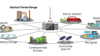
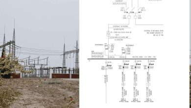
The substation is a complex ecosystem where power flow is managed, measured, and protected. The following components, working in concert, define the plant’s operational capability.
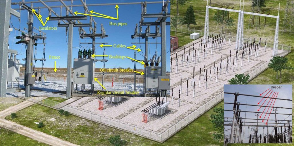
1. The Primary Movers: Transformers and Busbars
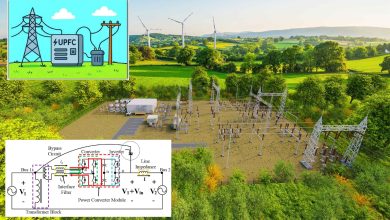
The Transformer is the fundamental workhorse, stepping up or stepping down voltage to facilitate efficient transmission across the grid or safe distribution to the local plant. Without this voltage conversion, power cannot reach its destination efficiently—the Busbars act as the central nervous system, distributing power across various feeders and circuits. The physical integrity of the busbar is paramount; even tiny hairline cracks or loose connections can create significant operational risks due to localized heating and potential flashovers.
2. The Guardians: Circuit Breakers and Protective Relays
The Circuit Breaker and Switchgear are the system’s primary defense mechanisms, designed to interrupt fault currents and isolate equipment for maintenance. A small failure in a breaker’s operation can halt an entire unit or, worse, lead to cascading failures across the grid.
The intelligence behind this defense lies with the Protective Relays. These silent guardians continuously monitor the system, detect abnormalities (such as short circuits or overloads), and instantly trigger corrective actions, primarily by commanding the circuit breakers to trip. The speed and selectivity of the relay system—its ability to isolate only the faulted section—are what prevent localized issues from becoming system-wide disasters.
3. The Eyes and Ears: Instrument Transformers (CTs/PTs)
The control and protection systems cannot function without accurate data. Instrument Transformers (Current Transformers, CTs, and Potential Transformers, PTs) provide the necessary isolation and scaling, transforming high primary currents and voltages into standardized, low-level signals (e.g., 5A or 120V) that relays and meters can safely handle. Misreadings from a saturated CT or an inaccurate PT can mislead operators and protection systems, causing a relay to fail to trip during a severe fault or to nuisance-trip during regular operation.
4. The Life Support: Auxiliary Systems and Grounding
Often overlooked, the Auxiliary Systems are arguably the most critical components for maintaining system intelligence during a fault. This includes Batteries and Uninterruptible Power Supplies (UPS). These DC systems are the “heartbeat” of the protection scheme; they provide the backup power necessary to energize the protective relays and, crucially, to supply the trip coils of the circuit breakers. A failure in the DC control power system can render the entire protection scheme useless, as the relays would be unable to command the breakers to open, allowing a fault to persist and cause catastrophic damage.
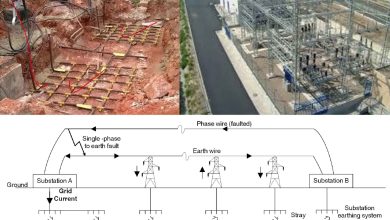
Finally, the Grounding System is the invisible shield that protects personnel and equipment from electrical faults. It provides a low-impedance path for fault currents, ensuring that protective devices operate correctly and, most importantly, limiting step and touch potentials to safe levels, thereby preventing electrocution.
Things to Avoid in Practice: The Interdisciplinary Blind Spots
Understanding the hidden interactions between these components sets senior engineers and supervisors apart. The most common failures in substation operation stem from neglecting the “minor” elements and the interdisciplinary nature of the work.
| Mistake | Consequence | Professional Insight |
| Neglecting Minor Components | Fuses, isolators, cable trays, and connectors are treated as optional or secondary. | These components are the weakest links; a single corroded connector can cause localized overheating and system failure. |
| Skipping Routine Inspections | Corrosion, loose connections, or worn components quietly escalate risks. | Proactive maintenance, including thermal imaging and vibration analysis, is essential for detecting precursors to failure before they become critical. |
| Over-reliance on Automation | Operators lose situational awareness and the ability to intervene manually when automation fails. | Automation is a tool, not a replacement for human judgment. Operators must maintain a deep understanding of manual intervention procedures. |
| Poor Labeling & Documentation | Misidentification leads to delays, mistakes, or accidents during critical operations. | As-built drawings and meticulous logs of all modifications are mandatory for safe and efficient long-term operation. |
| Ignoring Interdisciplinary Awareness | Electrical faults often look mechanical (e.g., a noisy transformer) and vice versa. | A holistic understanding of the system—thermal, mechanical, and electrical—is required for accurate root cause analysis. |
Key Insight for Professionals
A substation’s value is not the sum of its parts, but the product of their coordinated operation. The accurate measure of a robust substation is its ability to maintain control and protection during the most severe fault conditions. This capability relies entirely on the often-unseen auxiliary and control systems. Whether you are a junior engineer, technician, or director, knowing what truly drives a substation—the integration and interdependence—is the key to preventing costly mistakes.
Start safe, work safe, finish safe.
References
[1] IEEE Power and Energy Society. Instrument Transformers: Types and Testing.
[2] National Grid. Substation Auxiliary Systems. Highlighting the criticality of DC batteries for protection systems.
[3] IEEE Standard 80. Guide for Safety in AC Substation Grounding.