Power Cables Sheath Bonding Design Guide for High Voltage Systems
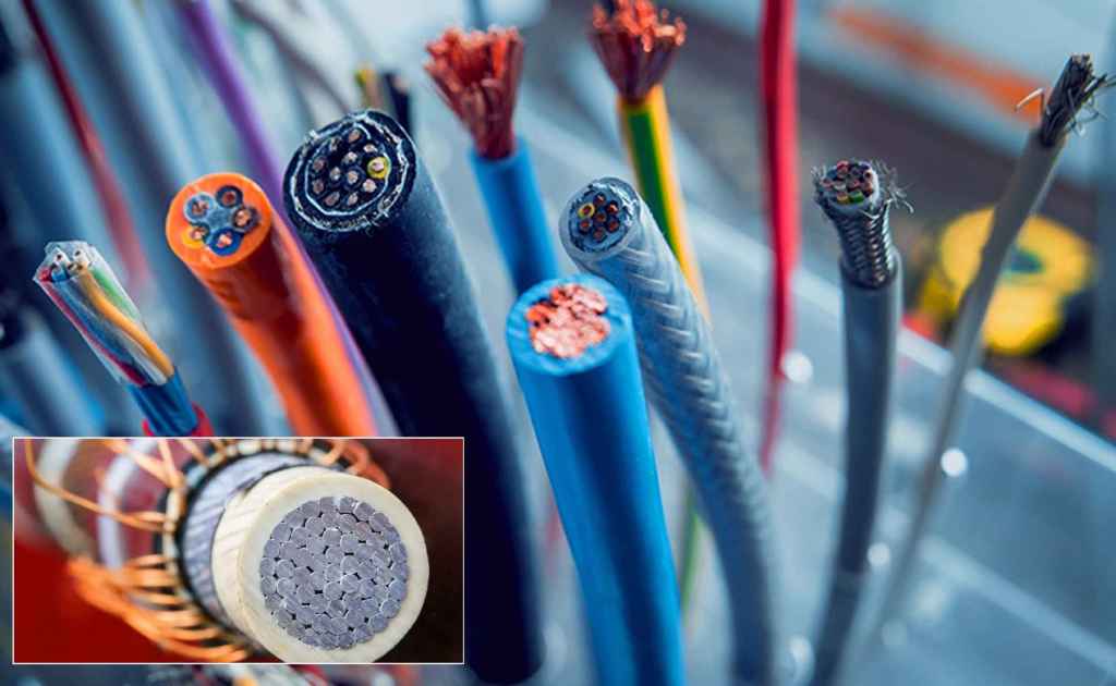
High-voltage power cables incorporate an outer concentric metallic layer, typically comprising a screen, sheath, and/or armor, collectively termed the “sheath.” This component serves several critical functions: providing a path for fault and capacitive charging currents, establishing an earth potential for personnel safety, and acting as a moisture barrier for the insulation system.
For circuits exceeding approximately 500 A, specialized sheath bonding arrangements are employed to mitigate sheath current losses. Although these configurations incur additional capital and maintenance costs, they frequently enable the use of cables with reduced conductor cross-sections for a given load current. The selected bonding arrangement represents the second most significant factor affecting cable current ratings, subordinate only to the external thermal resistance of the installed environment. Current ratings are determined in accordance with the IEC 60287 standard series.
A sheath bonding system is essential for insulating protection during normal operation and against transient overvoltages caused by lightning, switching operations, and fault conditions. Furthermore, it fulfills a vital safety role by controlling touch voltages.
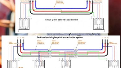
This report delineates four principal bonding methodologies: solid bonding, single-point bonding, cross-bonding, and impedance bonding. For extended high-voltage (HV) and extra-high-voltage (EHV) transmission lines, sectionized cross-bonding is the predominant configuration, whereas single-point bonding is typically reserved for shorter circuits.
Sheath Loss Mechanisms
The alternating magnetic field generated by current in the phase conductors induces currents within the metallic sheath via transformer action. These induced currents give rise to two distinct loss components:
- Circulating Current Losses: These occur when the bonding arrangement permits a continuous closed path for sheath current flow. Their magnitude is typically substantial and directly depends on the bonding method.
- Eddy Current Losses: Generated radially and longitudinally within the sheath due to skin and proximity effects, these losses are present irrespective of the bonding configuration but are generally lower in magnitude than circulating currents.
Both loss mechanisms produce ohmic heating within the cable, thereby reducing its ability to carry current. Circulating currents are prevalent in solidly bonded systems and multicore cables with individually sheathed cores. In single-point or cross-bonded systems, circulating currents are eliminated, though eddy current losses persist.
Sheath Bonding Design: Solid Bonding
Methodology
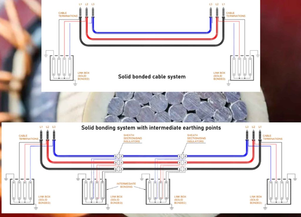
In a solid-bonding arrangement, the cable sheath is connected directly to earth at both ends of the cable route. Intermediate bonding points may also be installed along the route to maintain safety by limiting induced voltages should a terminal bond become disconnected.
Typical Application
This configuration is applied to short cable lengths with lower current ratings, low- and medium-voltage systems (typically up to 66 kV), and submarine cables. Its use in HV transmission systems is generally avoided due to the high associated losses.
Advantages
- Simplicity and low initial cost.
- Low external magnetic field due to the opposing sheath and conductor currents.
- Minimal maintenance requirements.
- Sheath voltage is maintained at earth potential throughout.
Disadvantages
- Induced circulating sheath currents can reach magnitudes up to 80% of the conductor current.
- Associated Joule heating de-rates the cable system, often necessitating larger conductor sizes to compensate for the capacity reduction.
Key Design Considerations
- Employ dual independent bonding leads at each earthing point to enhance reliability.
- Bonding leads must be sized to withstand prospective fault currents.
- The inclusion of intermediate earthing points is dependent on route length and system parameters.
- The magnitude of the circulating current is independent of the circuit length.