Power Cables Impedance Bonding Methodology for Cable Sheaths
Method
The impedance bonding technique involves the insertion of a defined impedance—such as a reactor or resistor—into the sheath current path. This is performed to limit the magnitude of circulating sheath currents under load conditions and to mitigate fault currents. The impedance may be implemented using standard reactors or more specialized devices, including saturable reactors or bonding transformers.
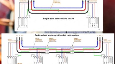
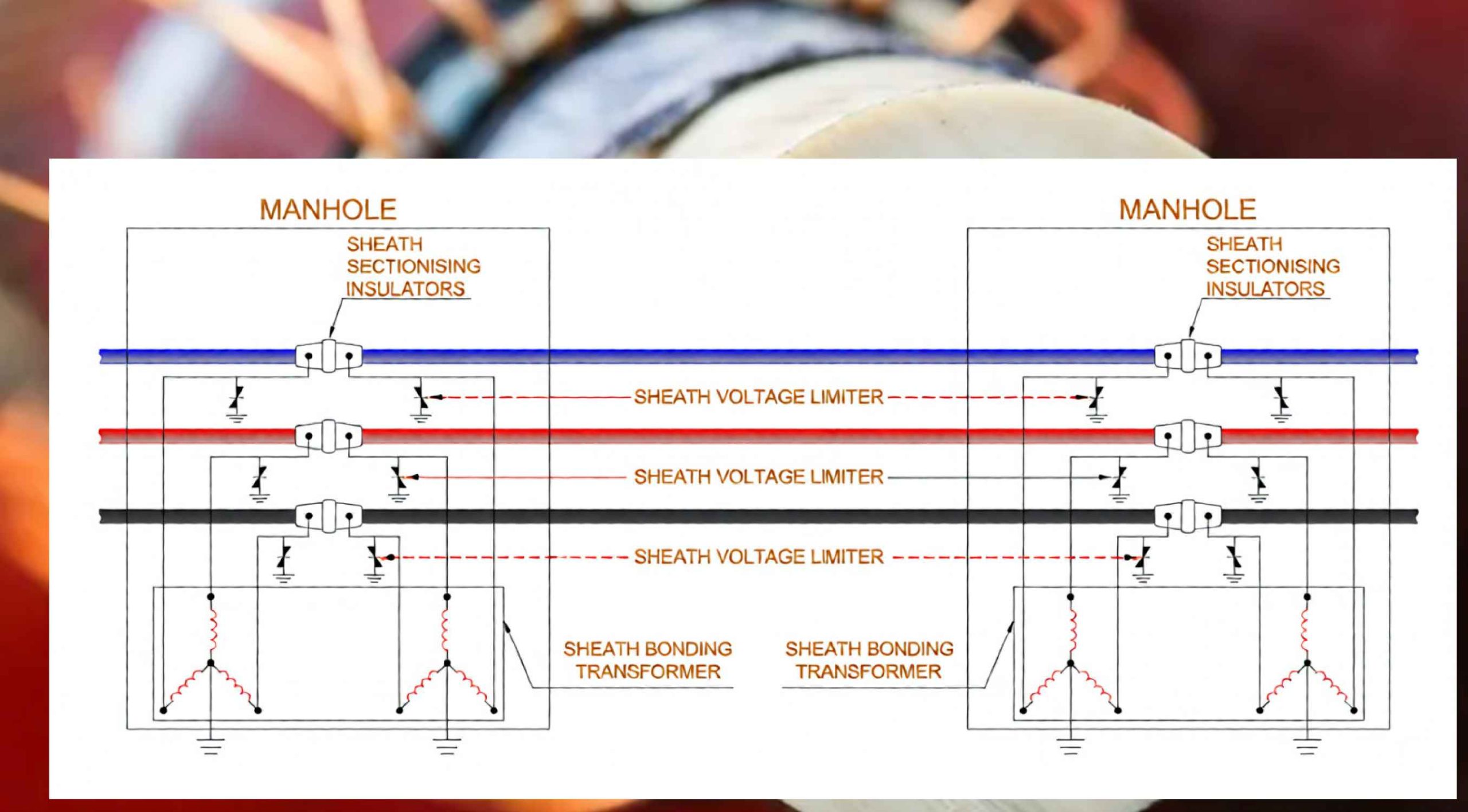
In the transformer-based sheath bonding configuration, both terminations of each cable sheath are electrically connected to a dedicated three-phase sheath bonding transformer, as illustrated in Figure 7.
Application Context
Impedance bonding methods are generally regarded as less satisfactory than alternative bonding schemes (e.g., cross-bonding, solid bonding) and are not recommended for general application. Their use may be justified in specific, isolated circumstances. For instance, bonding transformers can present an economical solution where suitable phase balancing for cross-bonding is unachievable and single-point bonding is inadmissible—such as in the absence of an empty duct for an earth continuity conductor (ECC). This method may also be employed when a spare cable is installed (e.g., a fourth cable for a single circuit). In such scenarios, reconfiguring a cross-bonding system upon deployment of the spare cable is a complex and time-intensive operation, whereas reconnection within a bonding transformer scheme is comparatively simple.
Advantages
A principal advantage of the bonding transformer scheme is its efficacy in limiting induced sheath circulating currents, irrespective of whether the spacing between cable joint bays (vaults) is equal or unequal.
Disadvantages
The method introduces several disadvantages:
- It requires additional physical space within cable vaults to accommodate the impedance devices.
- The requisite impedance devices are relatively costly, as their design must account for and withstand prospective fault current conditions.
- Under normal operating conditions, third-harmonic currents can be induced into the sheath, posing a risk of interference to adjacent telecommunication lines.
- Stray direct currents, which may enter the system via grounding connections, can lead to saturation of the magnetic iron cores within the reactors or transformers, thereby disrupting their intended operation.
Design Considerations
Key design considerations for impedance bonding include:
- Impedance devices are typically furnished with center taps or designated grounding points to facilitate connection to earth.
- Sheath bonding transformers must be specifically designed to avoid core saturation under the influence of sheath voltages induced by both normal and short-term emergency operating currents.
- Cable sheaths are additionally connected to local earth through sheath voltage limiters (SVLs) to control transient overvoltages.
Conclusion
Sheath bonding constitutes a critical design aspect for high-voltage power cable transmission systems, demanding careful engineering analysis. The selected bonding method fulfills multiple essential functions and exerts a substantial influence on both the total system cost and the current-carrying capacity (ampacity) of the cables.