Power Cables Cross-Bonding in High-Voltage Cable Systems
1. Principle and Methodology
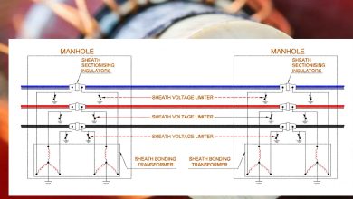
Cross-bonding is a standardized technique employed in three-phase high-voltage cable systems to mitigate power losses within the metallic sheaths. The method exploits the inherent phase relationship (120° displacement) of the induced sheath voltages. Through strategic sectionalization and interconnection of the sheaths, these voltages are vectorially summed, resulting in a near-neutralization of the net electromotive force across a defined major section. This minimization of the resultant voltage drastically reduces circulating sheath currents and associated losses.
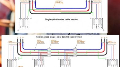
Operationally, the cable route is divided into minor sections. The sheaths are then cross-connected at the junctions between these sections—typically transposing the connection sequence (e.g., Phase A sheath to Phase B position)—so that the induced voltages over three successive minor sections sum to approximately zero. These three minor sections constitute one major section. For optimal voltage cancellation, transposition of the cable conductors themselves is recommended, though practical constraints often limit this for large, rigid cables.
2. Configurational Variants
Several implementation schemes exist, tailored to specific installation requirements:
- Continuous Cross-Bonding: Sheaths are cross-bonded at every minor section junction along the entire route. Solid bonding and grounding of all three sheaths together occur only at the two terminal ends of the circuit.
- Sectionalized Cross-Bonding: The route comprises multiple, discrete major sections in series. Sheaths are solidly bonded and earthed at the junctions between major sections and at the circuit ends, while cross-bonding via sheath voltage limiters (SVLs) is employed between minor sections within a significant section.
- Direct Cross-Bonding: Sheath transposition is performed without SVLs or link boxes. This simplifies maintenance by reducing the number of components but complicates disconnection for testing, potentially requiring physical cutting of bonding cables.
- Cross-Bonding of Short Lines: For circuits of intermediate length, a simplified approach using two minor sections with a central cross-bonding point (employing an SVL) is adopted to reduce circulating currents compared to solid bonding.
- Cross-Bonding in Tunnel Installations: Proximity allows for very short bonding leads. Direct cross-bonding is common, and SVLs are typically connected in a delta (rather than star) arrangement. This configuration necessitates SVLs with a higher voltage rating due to elevated induced voltages under normal and transient conditions. Bonding leads must be sized to withstand system short-circuit currents.
3. Applications, Merits, and Demerits
Application: Cross-bonding is the preferred and most prevalent method for longer cable circuits or where high fault currents would lead to excessive sheath voltages under alternative bonding schemes.
Advantages:
- Eliminates the practical length limitation inherent to single-point bonding.
- Significantly reduces sheath circulating currents, lowering losses and permitting higher cable ampacity.
- Provides a continuous, grounded metallic path along the cable circuit, enabling sheath currents to flow during earth faults. This obviates the need for a separate earth continuity conductor (ECC).
- The sheath itself acts as a more effective screening conductor during earth faults than a parallel ECC, thereby reducing induced voltages in adjacent infrastructure.
Disadvantages:
- Increased system complexity and cost.
- Requires careful design to ensure minor sections are of equal length for optimal voltage cancellation—a challenge in practical installations.
4. Key Design Considerations
A fundamental requirement for classic cross-bonding is a minimum of three cable sections (minor sections). Circuits comprising only one or two cable lengths cannot utilize this method and typically default to single-point bonding. Furthermore, residual circulating currents are often present due to inevitable minor imbalances in section lengths and cable spacings.
Permissible induced voltage levels and the voltage differences between sheaths and earth points constrain design. The most severe sheath-to-earth voltages in cross-bonded systems generally arise from two- or three-phase faults. Notably, if a cross-bonded cable circuit is inserted into an overhead line, single-phase faults—particularly with high earth impedances—can generate the highest sheath-to-earth voltages.