Methods to Reduce Step Potential and Touch Potential in Substations
Step potential and touch potential are critical safety considerations in electrical substations. During a ground fault, fault current flows into the earth through the substation grounding system and returns to the grounded transformer neutral. Because the transformer neutral is solidly grounded, a large portion of fault current can pass through the soil, creating significant voltage gradients across the ground surface and between grounded structures and nearby earth points. If not properly controlled, these voltage differences can pose serious risks to personnel working within or near the substation.
Understanding Step and Touch Potential
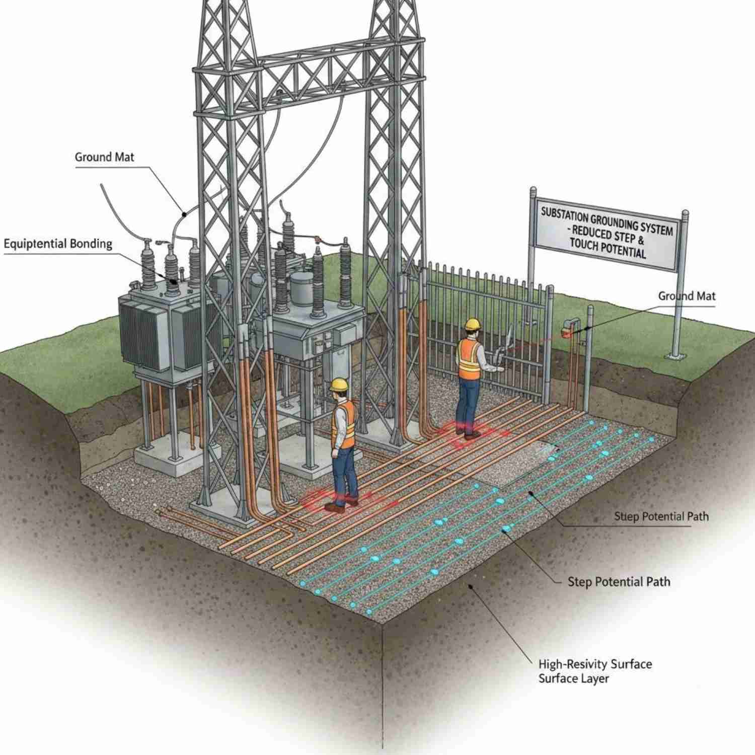
Step Potential occurs when a person standing on the ground experiences a voltage difference between their two feet. This happens because the ground surface is at different voltages at different points due to the voltage gradient created by the fault current. The current path in this case flows from one foot, up one leg, across the body, and down the other leg to the second foot.
Touch Potential occurs when a person touches a grounded structure (such as an equipment frame, fence, or metallic enclosure) while standing on the ground. The voltage difference between the object and the ground at the person’s feet can cause current to flow through the body, typically from hand to feet or hand to hand.
Both conditions can exist:
- Under normal operating conditions, Unbalanced loads may cause a rise in neutral-to-earth voltage. While usually not dangerous, this can still cause mild shocks.
- During ground faults, the risk is much higher due to large fault currents and steep ground-voltage gradients.
Because of this, substation design must ensure that step and touch voltages remain within permissible safety limits.
Methods to Reduce Step and Touch Potential
Reducing these hazards requires a combination of grounding design, surface treatment, and proper bonding practices.
1. Install an Effective Grounding Grid
A well-designed grounding grid is the primary method of controlling ground potential rise (GPR).
- Use a dense grid of buried conductors to distribute fault current more evenly.
- Extend the grid beyond the main equipment area to reduce edge effects.
- Increase the number of ground rods to improve connection with deeper soil layers.
- Design the grid based on soil resistivity studies to optimize conductor spacing and depth.
A properly designed grounding system minimizes surface voltage gradients.
2. Increase Surface Layer Resistivity
Adding a high-resistivity surface layer reduces the magnitude of current that can flow through a person’s body.
Common materials include:
- Crushed rock (gravel)
- Asphalt
- Concrete (where appropriate)
Crushed stone is commonly used because it significantly increases the contact resistance between a person’s feet and the soil. This helps reduce the current levels at the step and touch.
3. Bond All Metallic Structures
All exposed conductive parts must be bonded to the grounding grid, including:
- Equipment frames
- Support structures
- Fences
- Cable trays
- Neutral points
Proper bonding ensures that metallic objects remain at nearly the same potential during a fault, reducing dangerous voltage differences.
4. Control Ground Potential Rise (GPR)
Ground Potential Rise occurs when fault current enters the grounding system, elevating its voltage relative to the remote earth.
To reduce GPR:
- Increase the overall grounding system area.
- Use multiple ground rods and deep-driven electrodes.
- Interconnect grounding systems where permitted.
- Improve soil conductivity where feasible (e.g., soil treatment).
Lower GPR directly reduces step and touch voltages.
5. Optimize Grid Geometry
Adjusting the layout of the grounding conductors can significantly influence surface voltage gradients.
- Reduce conductor spacing in high-risk areas (near equipment and control panels).
- Add extra conductors around transformer locations.
- Provide gradient control mats at operating positions.
Localized improvements can greatly enhance safety.
6. Use Equipotential Mats
In areas where operators frequently stand (e.g., control panels or switch operating locations), install equipotential mats bonded to the ground grid.
These mats:
- Equalize the voltage between feet.
- Reduce touch voltage differences.
- Provide an additional safety layer during switching operations.
7. Perform Proper Design Calculations
Step and touch potentials must be calculated during the design stage using:
- Maximum ground fault current
- Fault clearing time
- Soil resistivity data
- Grid geometry
Design limits should comply with applicable safety standards (such as IEEE guidelines). Proper calculation ensures that permissible body current limits are not exceeded.
Conclusion
Step potential and touch potential are serious safety hazards in substations, especially during ground faults when large currents flow through the earth. Although normal operating conditions may create small neutral-to-earth voltages, fault conditions present the greatest risk. By implementing a well-designed grounding grid, increasing surface resistivity, bonding all metallic structures, and optimizing grid geometry, substations can maintain step and touch voltages within safe limits. Careful engineering during the design phase is essential to ensure personnel safety and reliable substation operation.