Essential Power System Requirements for Modern Data Centers
Data centers power today’s digital economy. From cloud computing and AI to banking, healthcare, e-commerce, and government systems, nearly every modern service depends on facilities that operate around the clock.
With data centers consuming roughly 1% of global electricity—and growing—electrical reliability, safety, and efficiency are no longer optional. They are mission-critical.
Behind every high-performing data center is a carefully engineered electrical infrastructure that delivers continuous, stable, and resilient power under all operating conditions. This article explores the essential power system requirements, design considerations, and industry standards that ensure uptime, safety, and compliance.
Why Power Systems Are Mission-Critical
Data centers differ from typical commercial or industrial facilities in one fundamental way: downtime is unacceptable.
Even seconds of power loss can result in:
- Server crashes
- Data corruption
- SLA violations
- Financial penalties
- Reputational damage
In large facilities, unplanned outages can cost hundreds of thousands of dollars per minute.
The Importance of Electrical Resilience
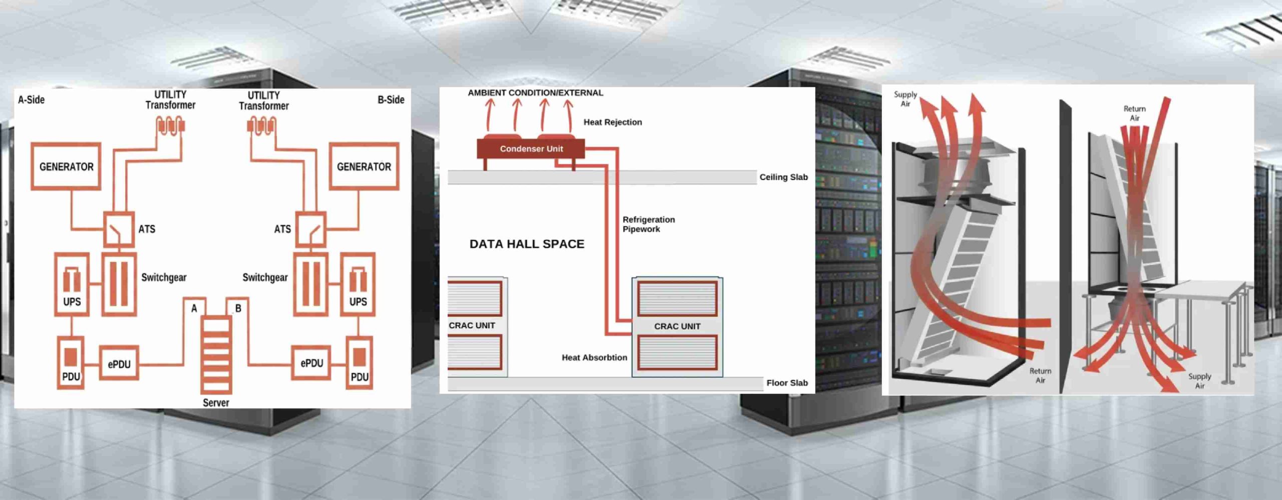
Data center electrical systems are engineered to maintain stable voltage and frequency—even during equipment failures or maintenance events. Every component must function as part of a coordinated and redundant network:
- Utility feeds
- Switchgear
- UPS systems
- Power distribution units (PDUs)
- Backup generators
Unlike office buildings, data centers operate under continuous, high-density loads. This constant demand amplifies the impact of disturbances, making precise system studies and protection coordination essential.
Types of Data Centers and Their Power Demands
Regardless of ownership or size, all data centers share one core requirement: uninterrupted power delivery.
Enterprise Data Centers
Privately owned facilities supporting internal IT operations.
- Size: Small to medium
- Reliability: Moderate
- Design Focus: Cost-effective resilience, scalable distribution, protection coordination for mixed loads
Colocation Data Centers
Third-party facilities lease space, power, and cooling to multiple tenants.
- Size: Medium to large
- Reliability: High
- Design Focus: Modular systems, strong grounding, flexible distribution, arc flash mitigation, and tenant isolation
Hyperscale Data Centers
Operated by cloud providers such as Amazon Web Services, Google Cloud, and Microsoft Azure.
- Size: Tens to hundreds of megawatts
- Reliability: Extremely high
- Design Focus: Advanced redundancy (N+1, 2N), energy optimization, thermal modeling, harmonic control for nonlinear loads
Power System Architecture and Design
Designing a data center electrical system requires detailed analysis of load behavior, redundancy strategy, and protection coordination.
Load Profiles and Power Flow
Data centers typically operate at near-constant load with occasional spikes during computational surges or expansion.
Accurate load flow studies help engineers:
- Identify voltage drops
- Evaluate transformer loading
- Minimize system losses
- Prevent bottlenecks
Typical Power Distribution Hierarchy
- Utility supply or on-site generation
- Main switchboards and switchgear
- Uninterruptible Power Supply (UPS) systems
- Power Distribution Units (PDUs)
- Rack-level power strips or busways
Each level must be fault-tolerant and coordinated to prevent a single failure from causing downtime.
Redundancy Models
Redundancy defines how well a data center can withstand equipment failure:
- N: No redundancy
- N+1: One additional backup unit
- 2N: Two fully independent systems
- 2N+1: Dual systems plus an extra backup
These configurations align with the Uptime Institute’s availability tiers (Tier I–IV).
Engineers evaluate multiple design scenarios to balance reliability, capital cost, and operational efficiency.
Contingency analysis further models how the system behaves during equipment outages, ensuring stability under worst-case conditions.
Critical Power Components
UPS Systems
Provide seamless power during outages and protect against voltage disturbances. Modern systems increasingly use lithium-ion batteries for longer life and improved energy density.
Generators
Automatically start during grid failure and support full facility load until utility power returns.
PDUs
Distribute conditioned power from UPS systems to IT racks while monitoring load balance.
Battery Energy Storage Systems (BESS)
Provide fast-response energy support and integrate with renewables or peak-shaving programs.
Thermal Sensitivity and Cable Ampacity
Heat is a major reliability risk in data centers. Excessive temperature can:
- Reduce conductor ampacity
- Degrade insulation
- Accelerate equipment aging
The Neher–McGrath Method
Accurate conductor sizing often uses the Neher–McGrath method, which calculates temperature rise based on:
- Current load
- Ambient temperature
- Conductor material and insulation
- Installation environment
Unlike simplified lookup tables, this analytical method accounts for both heat generation and dissipation—critical in tightly grouped cable environments typical of data centers.
Combining IEEE 835 data with Neher–McGrath modeling ensures safe, optimized conductor sizing and prevents unnecessary derating.
Compliance with Industry Standards
Two major standards guide electrical and environmental design:
ASHRAE Guidelines
ASHRAE TC 9.9 defines environmental classes (A1–A4) specifying allowable temperature and humidity ranges.
- A1: Strict limits for high-reliability equipment
- A2–A4: Wider ranges supporting energy-efficient designs
Cooling systems such as CRAC and CRAH units influence electrical loading, redundancy planning, and motor sizing.
Humidity control (typically 40–60%) prevents static discharge and protects IT hardware.
National Fire Protection Association (NFPA) – National Electrical Code
The NFPA 70 establishes safe electrical installation requirements.
Key applicable sections include:
- Article 645 – Information Technology Equipment
- Article 310 & 392 – Conductor ampacity and cable trays
- Article 250 – Grounding and bonding
- Article 240 – Overcurrent protection
Compliance ensures safety, inspection approval, insurance coverage, and regulatory adherence.
Energy Efficiency and Sustainability
Modern facilities must deliver both reliability and sustainability.
Power Usage Effectiveness (PUE)
PUE = Total Facility Energy / IT Equipment Energy
Leading hyperscale facilities target PUE values near 1.1, meaning nearly all energy supports IT operations.
Power system studies help identify inefficiencies such as:
- Transformer losses
- UPS inefficiency
- Harmonic distortion
- Load imbalance
Renewable Integration and Microgrids
Many data centers now incorporate:
- Solar generation
- Battery storage
- Microgrid architectures
Transient stability and protection coordination studies ensure seamless transitions between grid-connected and islanded operation.
The Role of Comprehensive Power System Studies
Ensuring uptime requires more than good design—it demands detailed engineering analysis.
Comprehensive studies typically include:
- Thermal and ampacity analysis
- Protective device coordination
- Arc flash hazard analysis (per NFPA 70E)
- Harmonic analysis
- Contingency and stability modeling
These evaluations provide:
- Optimized conductor sizing
- Proper relay and breaker coordination
- Reduced equipment stress
- Improved personnel safety
- Detailed compliance documentation
Final Thoughts
Modern data centers are among the most power-intensive and reliability-sensitive facilities in the world. Their electrical systems must be designed with precision, redundancy, and strict adherence to industry standards.
From load flow analysis and protection coordination to thermal modeling and renewable integration, comprehensive power system engineering is the foundation of uninterrupted uptime.
As digital infrastructure continues to expand, the importance of resilient, efficient, and compliant electrical design will only grow.