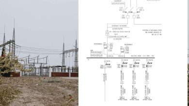
Demystifying the 11 kV HT Supply: A Deep Dive into the Single Line Diagram (SLD)
In the world of industrial power distribution, the Single Line Diagram (SLD) is the roadmap. It tells the story of how power flows from the utility grid to the smallest motor on the factory floor. For facilities operating at High Tension (HT)—typically 11 kV—understanding this diagram is not just about compliance; it is the foundation of safety, reliability, and operational efficiency.
Today, we are breaking down a standard 11 kV HT Supply to Factory scheme, designed in accordance with IEC/IS power system practices. Whether you manage a manufacturing plant, a data center, or a process industry, this is the blueprint that keeps your lights on and your machines running.
🖼️ System Overview
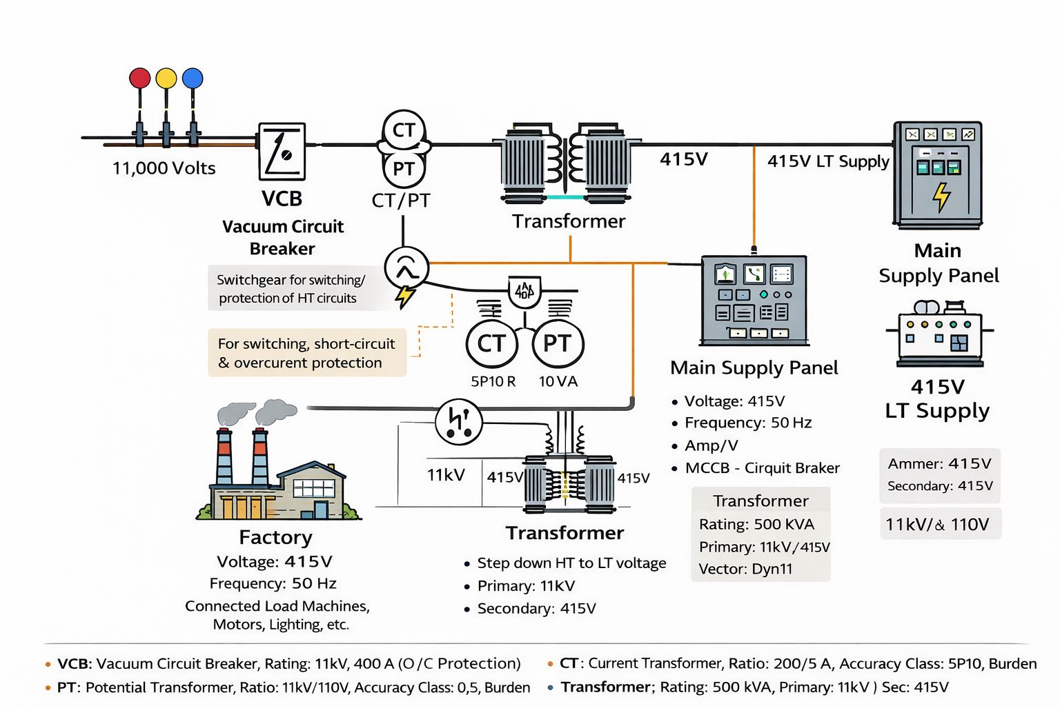
The setup begins with an 11 kV, 3-Phase, 50 Hz incoming supply from the utility. The primary goal of this system is to safely switch, protect, and meter the HT power before stepping it down to 415 V (LT) for utilization by factory loads.
Let’s walk through the critical components of this SLD, from the incoming line to the final load.
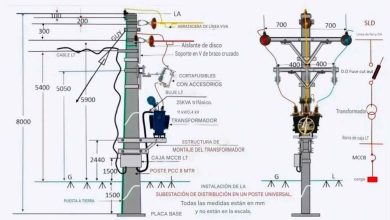
1️⃣ Incoming HT Line (11 kV)
The journey begins with the utility supply, delivered either via overhead lines or underground cables.
- Standard: IS 3427 / IEC 62271
- Function: This infrastructure must maintain proper insulation levels and clearances to withstand environmental stresses and system faults.
- Role: It serves as the entry point, feeding power directly into the main HT switchgear assembly.
2️⃣ VCB – The Guardian at the Gate
The first active component in the sequence is the Vacuum Circuit Breaker (VCB) .
- Function: Switching and protection of the HT circuit. It is designed to interrupt fault currents within a vacuum chamber, ensuring arc-free operation.
- Typical Ratings:
- Voltage: 11 kV
- Current: 400–630 A
- Breaking Capacity: 25 kA
- Protection: Controlled by a numerical relay providing Overcurrent (O/C) and Earth Fault (E/F) protection.
- Why VCB? It offers a long life, low maintenance requirements, and high reliability—essential for industrial environments where downtime is costly.
3️⃣ CT / PT Panel – The Sensory System
High voltage cannot be measured or monitored directly. The Current Transformer (CT) and Potential Transformer (PT) panel steps down the HT values to safe, measurable levels.
- Current Transformer (CT)
- Ratio: 200/5 A (typical)
- Accuracy Class: 5P10 (for protection)
- Role: Feeds the numerical relay for Overcurrent & Earth Fault protection; also supplies data for energy monitoring.
- Potential Transformer (PT)
- Ratio: 11 kV / 110 V
- Accuracy Class: 0.5
- Role: Provides voltage measurement for meters and relays, ensuring accurate billing and system monitoring.
4️⃣ Power Transformer – The Heart of the System
This is where the voltage transformation happens. The Power Transformer steps down the primary voltage (11 kV) to the usable secondary voltage (415 V).
- Typical Rating: 500 kVA (sizing varies by plant load)
- Vector Group: Dyn11
- Why Dyn11? This configuration is standard in industrial setups because it allows the neutral to be grounded on the LT side and handles unbalanced loads effectively.
- Cooling: ONAN (Oil Natural Air Natural)
- Role: It provides critical isolation between the hazardous HT system and the LT distribution network while supplying bulk power to the plant.
5️⃣ LT Main Supply Panel (415 V)
Once stepped down, the power enters the Low Tension (LT) domain. The LT Main Panel acts as the central distribution hub.
- Components:
- ACB / MCCB: Air Circuit Breakers or Molded Case Circuit Breakers for switching and fault protection.
- Busbars: Copper or aluminum bars distributing power to outgoing feeders.
- Protection & Metering: Monitoring voltage, current, power factor, and energy consumption.
- Connected Loads: This panel supplies all downstream loads, including Motor Control Centers (MCCs), lighting distribution boards, HVAC systems, and welding points.
6️⃣ Factory Load
The final destination of the power flow is the Factory Load. This includes motors, drives, heaters, and lighting systems.
To ensure these loads operate efficiently without penalties from the utility, power quality is maintained using:
- APFC Panels (Automatic Power Factor Correction): To maintain the power factor near unity.
- Harmonic Filters: Installed if non-linear loads (like VFDs) are present to mitigate harmonic distortion.
✅ Why This SLD Matters
A well-designed Single Line Diagram is more than just a drawing; it is a critical engineering deliverable. Here is why maintaining and understanding this specific SLD is vital:
- Clear Understanding of Power Flow: It provides a visual narrative of how power travels, making troubleshooting faster.
- Proper Equipment Sizing & Coordination: Ensures that the VCB, CTs, and cables are correctly rated to handle fault currents without nuisance tripping or catastrophic failure.
- Safe Isolation and Protection: It defines the zones of isolation, allowing maintenance crews to lock out specific sections safely (LOTO—Lockout/Tagout).
- Essential for Commissioning & Maintenance: A detailed SLD is the checklist for engineers during startup and routine maintenance.
- Mandatory for Audits & Approvals: Statutory authorities and insurance companies require an updated SLD for electrical safety audits and legal compliance.
🔌 Conclusion
The journey from an 11 kV utility incomer to a 415 V motor involves a carefully orchestrated sequence of switching, transformation, and protection. The Single Line Diagram encapsulates this complexity into a readable format.
Whether you are designing a new facility or maintaining an existing one, paying close attention to the VCB selection, CT/PT metering accuracy, and transformer vector grouping will pay dividends in reliability and safety.