Mastering Cable Pulling: A Guide to Tension and Sidewall Pressure Calculations
Successful cable installation is a precise engineering feat, where exceeding mechanical limits can lead to costly damage, delays, and failures. At the heart of a safe and efficient pull lie two critical parameters: cable pulling tension and sidewall pressure. This article breaks down their importance, calculations, and best practices for planning a successful installation.
The Critical Pre-Pull Route Inspection
Before any cable is pulled, a thorough route inspection is non-negotiable. This proactive step is designed to:
- Prevent exceedances: Identify bends and potential pulling tensions that surpass the cable’s specified limits.
- Avoid jamming: Check for clearance issues that could cause cables to jam inside conduits.
- Optimize direction: Determine whether a forward or reverse pull will result in lower forces.
- Plan equipment placement: Assist in positioning winches or push/pull machinery with accurate force requirements.
Ignoring this step risks cable damage, installation failure, and compromised long-term reliability.
Understanding Cable Pulling Tension
Cable pulling tension is the cumulative force required to move the cable through the conduit or tray system. It is the paramount parameter for assessing any installation, essential for planning and validating the cable design, route, and methodology.
- In straight sections, tension adds incrementally.
- At bends, the incoming tension is multiplied, creating a force “hump.”
- The highest tension is typically at the pulling end, though significant downhill sections or the use of intermediate push/pull devices can alter this.
- Pulling direction matters significantly. Lower tensions are generally achieved by feeding cable into the end of the run with the most bends or into the uphill side.
Industry surveys indicate average maximum pull lengths are around 850m (urban) and 1185m (rural), with specialized techniques enabling pulls over 2km. These extremes underscore the necessity of detailed pulling studies before finalizing a route, often performed with specialized software such as Cable Pro Web.
Maximum Allowable Cable Tension
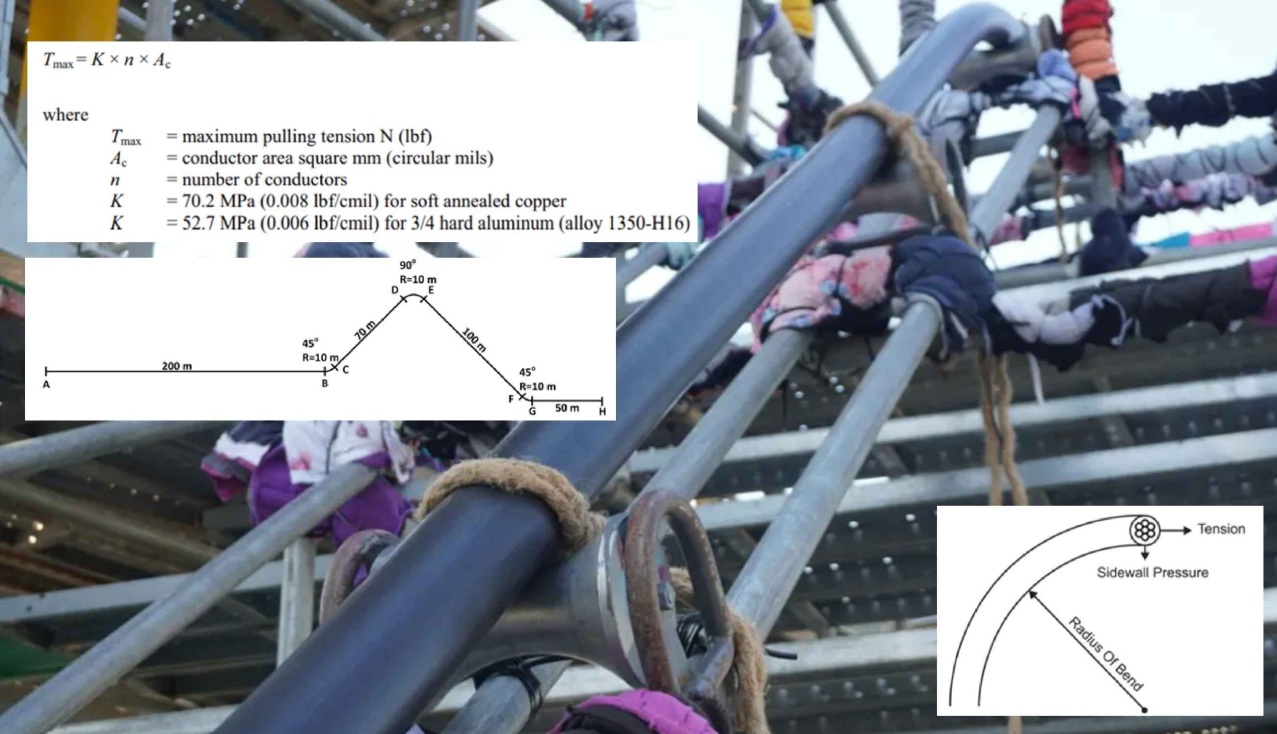
The Maximum Allowable Pulling Tension is defined by the cable’s construction and provided by the manufacturer. In the absence of specific data, established equations offer guidance. A common formula for pulling by the conductor is:
T_max = k * N * A
Where T_max is the maximum tension, k is a constant (e.g., 70 for copper, 40 for aluminum), N is the number of conductors, and A is the conductor cross-sectional area.
Notably, due to uneven force distribution, a standard three-core cable can typically withstand approximately twice the allowable tension of a single-core cable (e.g., 44,500N vs. 22,250N).
The Critical Role of Sidewall Pressure
Sidewall Pressure (SWP) is the normal force pushing the cable against the inner radius of a conduit bend. It is a function of the tension exiting the bend and the bend’s radius. If there are no bends, there is no sidewall pressure. This localized force is crucial; excessive SWP can crush or deform cable shielding and insulation.
Maximum Allowable Sidewall Pressure (MASP) varies by cable type:
- Power & Control Cables: Typically 4,380 – 7,300 N/m of bend radius.
- Instrumentation Cables: 4,380 – 7,300 N/m (construction dependent).
- Armoured Cables: Often 4,380 N/m or lower.
Performing the Calculations
Calculating cumulative tension and SWP involves applying specific equations to each segment of the run: straight horizontal sections, slopes, horizontal bends, vertical bends, and sections with rollers or push/pull assist. Modern engineering software automates these complex, iterative calculations, ensuring accuracy and accounting for variables like friction.
Additional Critical Checks: Clearance & Jamming
When pulling multiple cables, two additional calculations are vital:
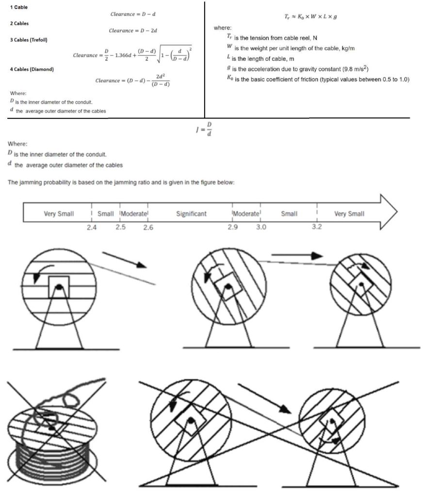
- Cable Clearance: The gap between the top cable and the conduit must be at least 10% of the conduit’s inner diameter (or 1 inch for large/bend-heavy runs) to prevent binding.
- Jamming Ratio: This predicts the tendency for cables to wedge (jam) in a bend, typically occurring when the conduit inner diameter (ID) is between 1.05 and 1.1 times the cable bundle diameter (for three cables in a triangular formation). The ratio is calculated as Conduit ID / Cable Diameter.
The Starting Point: Reel Back Tension
The initial force required to pull the cable off the drum—reel back tension—must be included in the total tension calculation. This depends on cable weight, stiffness, and reel stand condition. Proper payoff technique (pulling from the top of a vertical reel or underneath a horizontal reel) is essential to minimize this initial force and prevent cable twisting.
Practical Calculation Example
Using Cable Pro Web software, an analysis was performed to pull 3 x 500 mm² Cu XLPE/PVC single-core cables (37mm diameter, 491 kg/100m) through a 125mm conduit.
Key Findings:
- Pulling Direction: Pulling from Location H required 20% less force than from Location A.
- Lubrication: Using cable lubricant (reducing the coefficient of friction from 0.5 to 0.25) decreased the total tension by 67%.
- All Limits Met: In all simulated scenarios, neither the maximum cable tension (10.6 kN/cable) nor the MASP (14,225 N/m) was exceeded.
Sample Results (Pulling from Location A, Dry):
| Location | Tension (N) | Sidewall Pressure (N/m) |
|---|---|---|
| A (Start) | 0 | 0 |
| C (After 1st Bend) | 2,233 | 78 |
| E (After 2nd Bend) | 6,127 | 214 |
| H (End) | 8,439 | 0 |
Conclusion
Accurate cable pulling calculations are not an optional luxury but a fundamental requirement for a reliable electrical installation. By rigorously pre-inspecting the route, understanding tension and sidewall pressure limits, and utilizing modern calculation tools or software, engineers can design pulls that protect cable integrity, ensure personnel safety, and guarantee long-term system performance.
References:
- IEEE Std. 1185-2019, Recommended Practice for Cable Installation in Generating Stations and Industrial Facilities.
- CIGRE TB 889-2022, The Installation of Underground HV Cable Systems.