Derating Factors for Cable Current-Carrying Capacity
Abstract
This document examines the critical influence of installation and environmental conditions on the current-carrying capacity (ampacity) of electrical cables. The principle of cable derating is introduced, whereby tabulated current ratings, established under standard reference conditions, must be adjusted via calculated correction factors to ensure safe operation under real-world project specifications. A systematic review of the primary derating parameters—including ambient temperature, soil thermal resistivity, and circuit grouping—is provided, with reference to international standards such as IEC 60364-5-52, AS/NZS 3008.1, and BS 7671. The discussion concludes with practical guidance on applying derating factors and identifies specific installation scenarios in which such corrections may be omitted.
1.0 Introduction: The Necessity of Cable Derating
The rated current-carrying capacity of a cable is not an intrinsic property but is contingent upon its ability to dissipate the heat generated by Joule (I²R) losses. Installation conditions and the external thermal environment significantly affect this heat dissipation, thereby altering the effective ampacity. For instance, a given cable will exhibit a lower current rating when buried in soil than when installed in free air, primarily due to differences in thermal resistance. Consequently, international cable sizing standards provide current rating tables based on fixed, standardized installation conditions. To accommodate deviations from these reference conditions, complementary tables of derating (or correction) factors are supplied. The application of these factors, which most often reduce but may occasionally increase the permissible current, is essential to prevent conductor temperatures from exceeding insulation limits, thus ensuring long-term cable integrity and system safety.
2.0 Primary Parameters Affecting Cable Ampacity
Several interdependent factors modify the current rating of a cable. The following nine parameters are fundamental to accurate derating calculations:
- Ambient Temperature: The temperature differential between the conductor and its surroundings governs heat dissipation. Cables installed in colder ambient conditions exhibit a higher ampacity than identical cables in hotter environments. Standard reference ambient temperatures vary by region and are codified in documents such as IEC 60287-3-1.
- Depth of Burial: For directly buried cables, increased burial depth elevates the thermal resistance between the conductor and the earth’s surface, impairing heat dissipation and necessitating derating. Standard reference depths are 0.5 m or 0.7 m (as assumed in BS 7671).
- Soil Thermal Resistivity (ρ): A critical parameter for buried installations, soil thermal resistivity varies with composition, moisture content, and seasonal conditions. Cable loading itself can cause localized soil drying (“thermal runaway”), increasing ρ. Typical values range from 0.8 K·m/W (damp clay) to over 2.5 K·m/W for dry, sandy soils, with a standard reference value of 1.2 K·m/W.
- Load Factor (Variable Loading): Standard ratings assume 100% continuous load. For cables subject to intermittent or cyclical loading where steady-state temperature is not reached, the effective ampacity may be uprated based on the load factor and duty cycle.
- Thermal Insulation: Cables installed within or in contact with thermally insulating materials experience restricted heat flow, requiring significant derating.
- Solar Radiation (Direct Sunlight): Exposure to direct sunlight can impart a substantial radiant heat load. Empirical data suggests this can elevate cable surface temperatures by approximately 20°C, mandating a corresponding derating for cables installed in outdoor, unshaded locations.
- Harmonic Currents: The presence of triplen harmonics (3rd, 9th, etc.) increases RMS current and induces additional losses in the neutral conductor of three-phase systems. This elevates the total heat generation within the cable bundle, necessitating derating.
- Circuit Grouping (Mutual Heating): Multiple cables or circuits installed in close proximity (in trays, conduits, or trenches) mutually heat one another, reducing the effective ampacity of each. Derating factors account for the number of circuits, their arrangement, and spacing.
- Enclosures: Cables installed within conduits, ducts, or other enclosures have reduced convective cooling. The derating is more severe when multiple cables are in a single enclosure.
3.0 Exceptions to Derating Requirements
Under specific conditions, the application of derating factors may be omitted. The standard AS/NZS 3008.1 provides illustrative examples, including:
- Mineral Insulated Metal Sheathed (MIMS) cables without an external covering, unless installed adjacent to other cables.
- Grouped sections of limited length (e.g., ≤ 1 m for smaller conductors or ≤ 3 m for larger conductors, or half the total cable length—whichever is shorter).
- Cables are continuously operating at less than 35% of their tabulated current rating.
Note on Standard Interchangeability: While rating methodologies in major standards (IEC, AS/NZS, BS) are generally derived from IEC 60287, caution must be exercised when interchanging factors, as the defined standard conditions (e.g., reference ambient temperature) differ geographically.
4.0 Methodology for Applying Derating Factors
The derating process follows a systematic three-step procedure:
- Establish Base Rating: Obtain the standard current rating (Iₜ) for the cable type, size, and standard installation method from the applicable reference tables.
- Determine Correction Factors: Identify all relevant derating factors (C₁, C₂, … Cₙ) from the standard’s correction tables that correspond to the project’s actual installation conditions.
- Calculate Derated Ampacity: Compute the adjusted current-carrying capacity (Iᵣ) using the product of all individual factors:
Iᵣ = Iₜ × C₁ × C₂ × … × Cₙ
5.0 Reference Derating Factor Tables (AS/NZS 3008.1 Context)
The following tables are excerpted from AS/NZS 3008.1.1 (Australian conditions) and AS/NZS 3008.1.2 (New Zealand conditions). The standards are essentially identical, with notable divergence in ambient temperature tables.
Installation in Air:
- Table 22: Circuit grouping factors for bunched cables.
- Table 23: Factors for cables on perforated trays.
- Table 24: Factors for cables on ladder supports or unperforated trays.
Ambient Temperature Corrections:
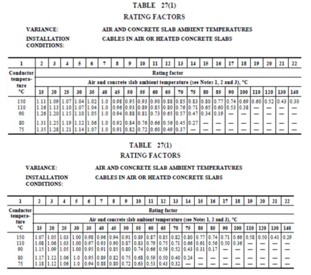
- Table 27(1): Derating factors for ambient air and concrete-slab temperatures (Australia).
- Table 27(1) – NZ: Derating factors for ambient air and concrete-slab temperatures (New Zealand).
- Buried Installations:
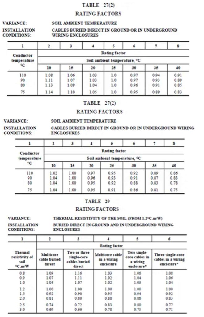
- Table 27(2) & 27(2)-NZ: Soil ambient temperature and thermal resistivity factors.
- Table 29: Factors for cables buried in enclosures.
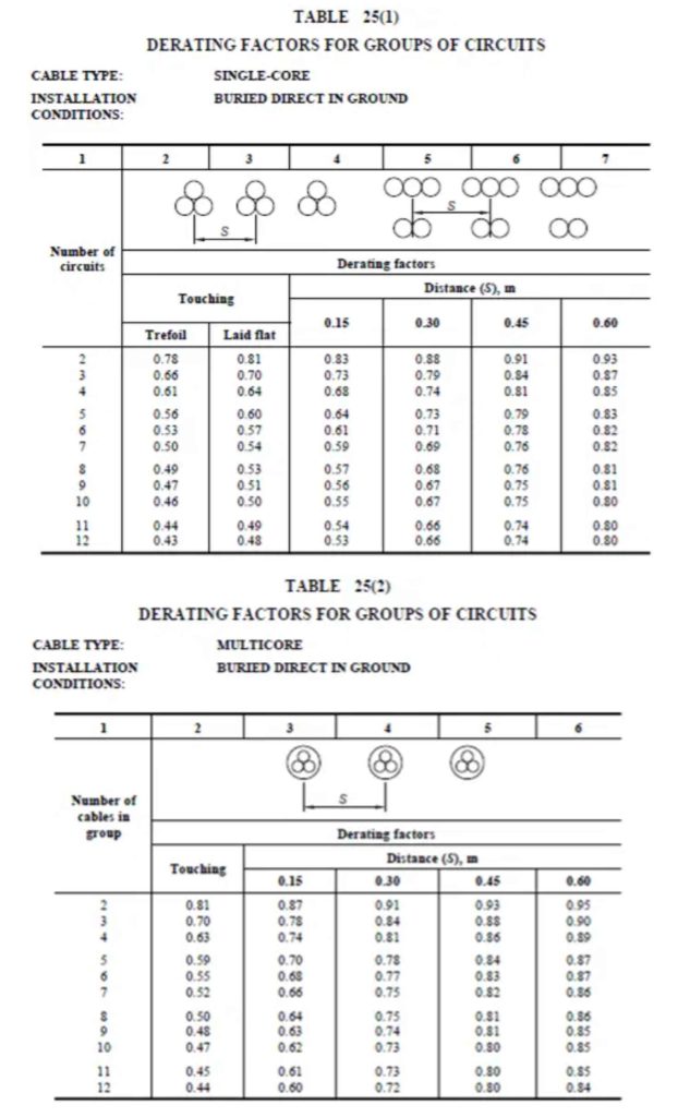
- Table 25(1) & 25(2): Grouping factors for directly buried single-core and multicore cables.
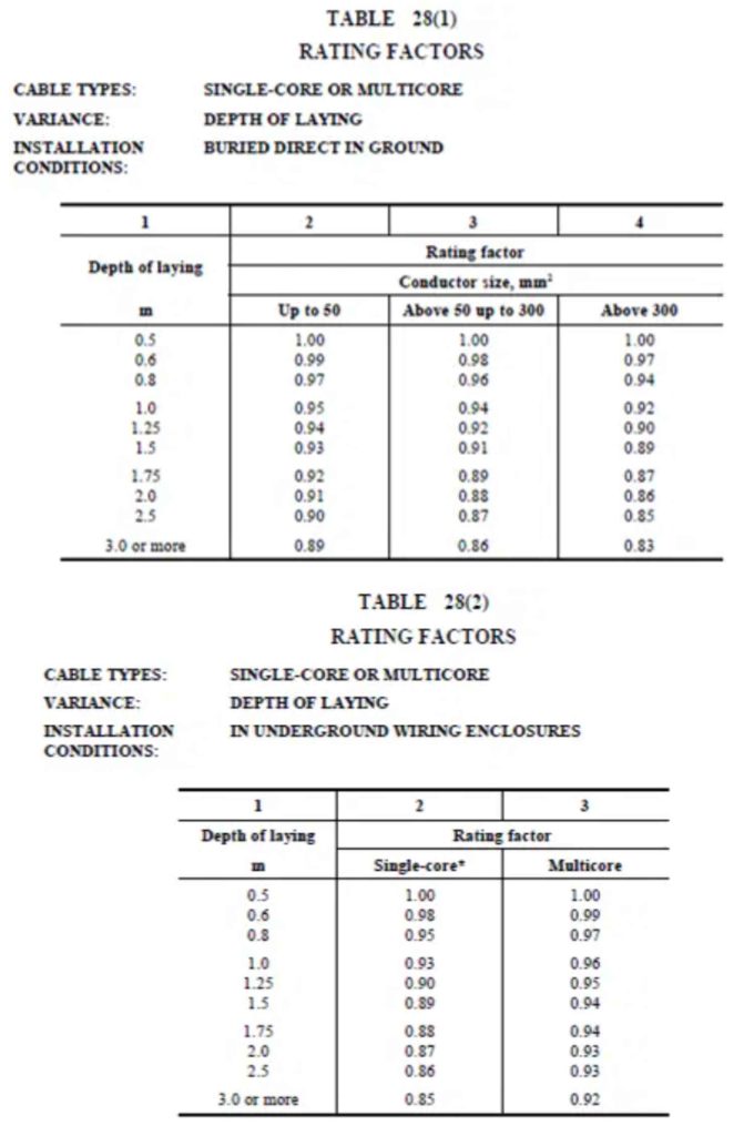
- Table 28(1): Depth of burial factors for directly buried cables.
- Table 28(2): Depth of burial factors for cables in buried enclosures.
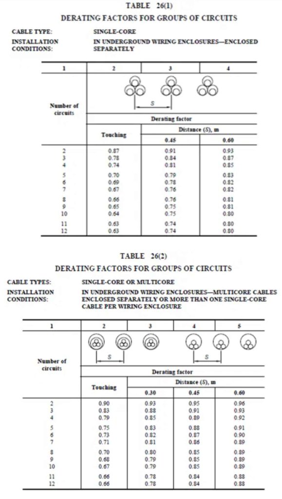
- Table 26(1) & 26(2): Grouping factors for buried cables within enclosures.
Disclaimer: The tables presented herein are for illustrative purposes. For design purposes, the complete tables and all associated notes from the full standard must be consulted. No responsibility is assumed for the accuracy or applicability of these excerpts.