كتاب «جودة التغذية الكهربية» للدكتورة كاميليا يوسف محمد
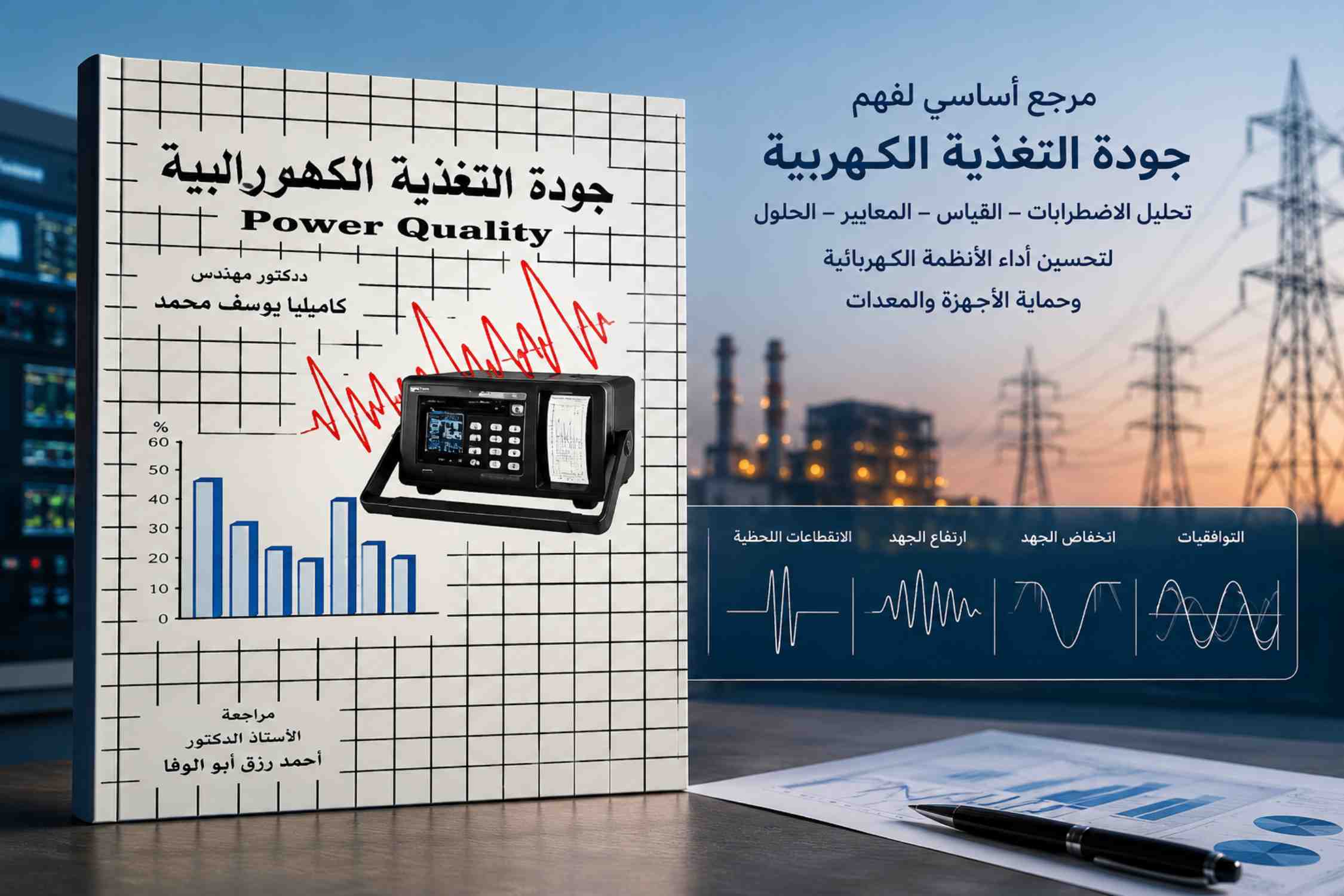
يُعد كتاب «جودة التغذية الكهربية – Power Quality» للدكتورة كاميليا يوسف محمد من الكتب العربية المتخصصة المهمة في مجال الهندسة الكهربائية، حيث يتناول أحد أكثر الموضوعات تأثيرًا في الأنظمة الكهربائية الحديثة، وهو موضوع جودة الطاقة الكهربائية وتأثير الاضطرابات على كفاءة التشغيل والأجهزة الصناعية والإلكترونية.
تكمن أهمية هذا الكتاب في أنه يربط بين الجوانب النظرية والتطبيقية لجودة التغذية الكهربية، موضحًا أسباب المشكلات الكهربائية مثل انخفاض وارتفاع الجهد، التوافقيات، الوميض الكهربائي، والانقطاعات اللحظية، مع بيان تأثير كل منها على المعدات المختلفة. وقد خصصت المؤلفة فصولًا متعددة لتصنيف الاضطرابات الكهربائية وشرح مصادرها وطرق قياسها ومعالجتها، مما يجعل الكتاب مرجعًا علميًا وعمليًا للطلاب والمهندسين.
ومن أبرز ما يميز الكتاب اعتماده على المعايير العالمية الحديثة مثل IEC وIEEE، حيث يوضح الحدود القياسية المقبولة للتوافقيات والانخفاضات والانحرافات في الجهد والتردد، الأمر الذي يساعد القارئ على فهم كيفية تقييم جودة الشبكات الكهربائية وفق الأسس العلمية الدولية. كما يعرض الكتاب العديد من الرسوم البيانية والجداول التوضيحية التي تسهّل فهم الظواهر الكهربائية المعقدة.
كما تبرز أهمية الكتاب في مواكبته للتطور التكنولوجي واعتماد المصانع والمنشآت الحديثة على الأجهزة الإلكترونية الدقيقة والحواسيب وأنظمة التحكم، وهي أجهزة تتأثر بشدة بأي اضطراب في التغذية الكهربائية. لذلك يوضح الكتاب وسائل الحد من هذه الاضطرابات باستخدام المرشحات، وأنظمة التعويض، وتحسين تصميم الشبكات الكهربائية، مما يساهم في رفع كفاءة التشغيل وتقليل الأعطال والخسائر الاقتصادية.
ويُعتبر الكتاب أيضًا مصدرًا عربيًا نادرًا في هذا التخصص الدقيق، حيث يوفر محتوى علميًا باللغة العربية بأسلوب واضح ومنظم، مما يسهّل على الطلاب والباحثين العرب دراسة موضوع جودة الطاقة دون الحاجة إلى الاعتماد الكامل على المراجع الأجنبية. وقد تناولت المؤلفة المفاهيم الأساسية مثل التوافقيات والوميض الكهربائي وانخفاضات الجهد بأسلوب تدريجي مدعوم بالأمثلة التطبيقية.
وفي الختام، فإن كتاب «جودة التغذية الكهربية» يمثل إضافة علمية مهمة للمكتبة الهندسية العربية، لما يحتويه من معلومات متخصصة وتطبيقات عملية تساعد على فهم مشكلات الشبكات الكهربائية الحديثة وطرق تحسينها. ولذلك يُعد مرجعًا مهمًا لطلاب الهندسة الكهربائية، والباحثين، والمهندسين العاملين في مجالات القوى والطاقة والصناعة.