دليل العدادات مسبقة الدفع للدكتورة كاميليا يوسف محمد
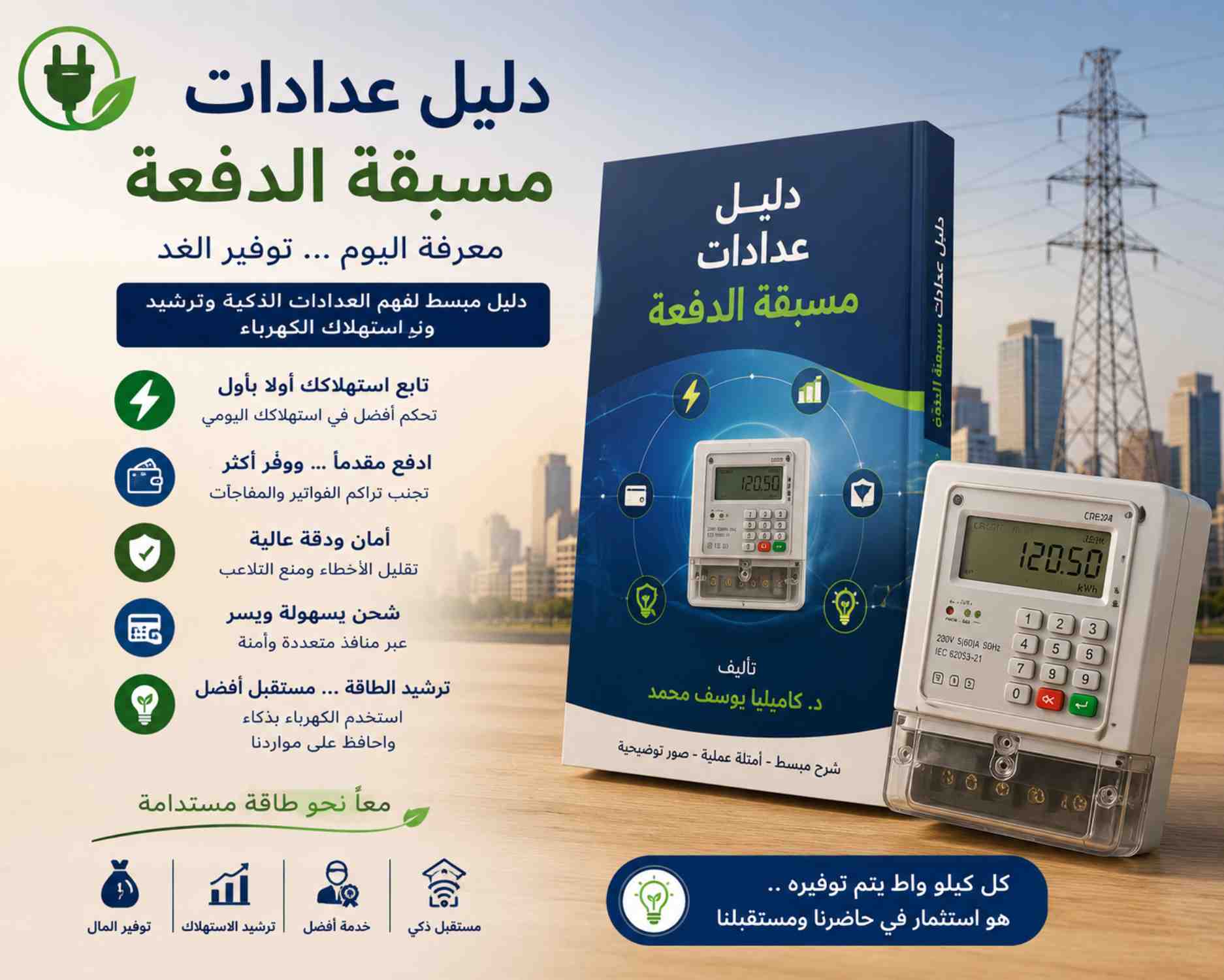
في ظل التطور الكبير الذي يشهده قطاع الكهرباء والطاقة، أصبحت العدادات مسبقة الدفع من أهم الحلول الحديثة التي تساعد على ترشيد الاستهلاك وتحسين إدارة الطاقة داخل المنازل والمؤسسات. ومن هنا تأتي أهمية كتاب “دليل عدادات مسبقة الدفعة” للدكتورة كاميليا يوسف محمد، الذي يُعد مرجعًا توعويًا مبسطًا يشرح كل ما يتعلق بالعدادات الذكية وآلية عملها وفوائدها للمستهلك والدولة على حد سواء.
لماذا يعتبر هذا الكتاب مهمًا؟
يتميز الكتاب بأسلوبه السهل والمنظم، حيث يشرح مفاهيم الكهرباء والطاقة بطريقة تناسب جميع القراء، سواء كانوا متخصصين أو مستخدمين عاديين. كما يقدم معلومات دقيقة حول كيفية تشغيل العدادات مسبقة الدفع، وطرق حساب الاستهلاك، وأساليب الشحن، بالإضافة إلى توضيح الرموز والإشعارات التي تظهر على شاشة العداد.
نشر ثقافة ترشيد الاستهلاك
من أبرز أهداف الكتاب تعزيز الوعي بأهمية ترشيد استهلاك الكهرباء، خاصة في ظل ارتفاع الطلب على الطاقة. فالكتاب يوضح كيف تساعد العدادات مسبقة الدفع المستخدم على مراقبة استهلاكه بشكل يومي، مما يدفعه إلى تقليل الهدر والتحكم في المصروفات الكهربائية بطريقة أفضل. كما يقدم أمثلة عملية لحساب استهلاك الأجهزة المنزلية المختلفة، وهو ما يساعد الأسرة على إدارة استهلاكها بذكاء.
دعم التحول الرقمي في قطاع الكهرباء
يتناول الكتاب أيضًا الدور الكبير للعدادات الذكية في تطوير خدمات الكهرباء وتحسين كفاءة التحصيل وتقليل الفاقد. فالعدادات مسبقة الدفع تعتبر جزءًا من التحول الرقمي الذي تتبناه وزارة الكهرباء، حيث توفر بيانات دقيقة وفورية عن الاستهلاك، وتساعد في تقليل الأخطاء البشرية ومشكلات الفواتير التقليدية.
مميزات العدادات مسبقة الدفع
يستعرض الكتاب مجموعة من المميزات المهمة للعدادات الحديثة، ومنها:
- متابعة الاستهلاك أولًا بأول.
- تجنب تراكم الفواتير الشهرية.
- تقليل فرص التلاعب أو الأخطاء في القراءة.
- إمكانية الشحن بسهولة عبر منافذ متعددة.
- تحسين كفاءة استخدام الطاقة داخل المنزل.
أسلوب توعوي مبسط
ما يميز هذا الدليل أنه لا يقتصر على الجانب التقني فقط، بل يقدم محتوى توعويًا مدعومًا بالرسومات والأمثلة والصور التوضيحية التي تسهل فهم المعلومات، مما يجعله مناسبًا للطلاب والعاملين بقطاع الكهرباء وكذلك المواطنين الراغبين في فهم نظام العدادات الحديثة. كما يربط بين التكنولوجيا الحديثة وأهمية الحفاظ على الطاقة باعتبارها موردًا أساسيًا للتنمية.
خاتمة
يُعد كتاب “دليل عدادات مسبقة الدفعة” للدكتورة كاميليا يوسف محمد من الكتب المهمة التي تسهم في نشر الوعي بثقافة ترشيد الكهرباء وفهم التكنولوجيا الحديثة في إدارة الطاقة. فهو ليس مجرد دليل تقني، بل أداة تثقيفية تساعد المجتمع على الاستخدام الأمثل للكهرباء، وتدعم جهود الدولة نحو التحول الرقمي وتحقيق كفاءة الطاقة. لذلك يُنصح بقراءته لكل من يرغب في فهم العدادات الذكية والاستفادة منها بشكل صحيح.