Analysis of Three-Phase Transformer Winding Configurations
I. Introduction
Three-phase power systems rely on transformers to efficiently step up or step down voltage levels for transmission and distribution. A three-phase transformer can be realized either by connecting three individual single-phase transformers to form a three-phase transformer bank or by using a single unit with three sets of windings on a common core. The configuration of the primary and secondary windings is a critical design choice, as it fundamentally determines the output voltage characteristics, the presence of a neutral point, and the transformer’s response to unbalanced loads and system disturbances. The two primary methods for interconnecting the windings are the Delta (Δ) configuration and the Wye (Y) or Star configuration. The flexibility to combine these configurations allows the transformer to be customized to meet the application’s specific voltage and grounding requirements.
II. Standard Winding Configurations
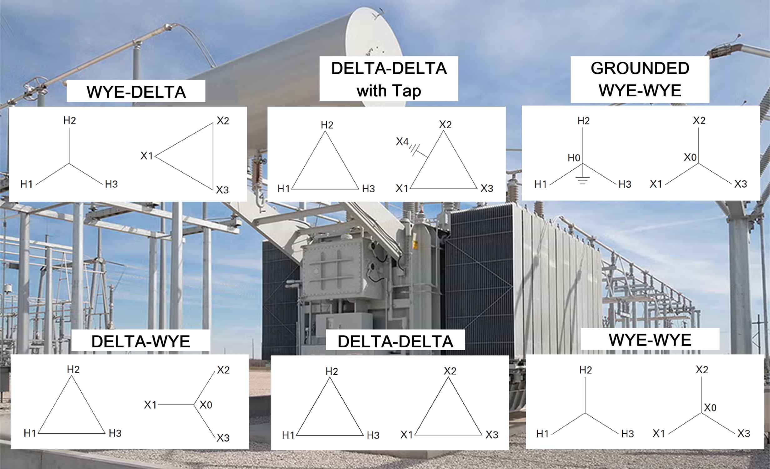
The four fundamental winding connections, along with a specialized grounded variation, are detailed below, highlighting their key operational characteristics.
A. Delta-Wye (Δ-Y) Connection
The Δ-Y connection is arguably the most popular transformer connection globally, particularly in distribution systems. The primary side is connected in Delta, and the secondary side is connected in Wye.
| Characteristic | Detail |
| Angular Displacement | 30 |
| Neutral Point | The Wye secondary provides a neutral point (X0) for supplying line-to-neutral loads. |
| Grounding Suitability | Suitable for both ungrounded and effectively grounded sources. |
| Service Type | Suitable for a three-wire service or a four-wire grounded service when the neutral (X0) is grounded. |
| Zero-Sequence Current | Zero-sequence currents in the secondary lines do not flow into the primary lines. Instead, they circulate within the closed Delta primary winding, which acts as a path for these currents. |
| Load Balance | The Delta primary winding provides superior current balance for the primary source, even when the secondary supplies large amounts of unbalanced loads. |
| Ground Source | When the secondary neutral (X0) is grounded, the transformer effectively acts as a ground source for the secondary system. |
B. Wye-Delta (Y-Delta) Connection
The Y-Δ connection is often employed in step-down applications where a stable primary neutral is available, but a secondary neutral is not required.
| Characteristic | Detail |
| Angular Displacement | 30 |
| Grounding Suitability | Suitable for both ungrounded and effectively grounded sources. |
| Service Type | Suitable for a three-wire service or a four-wire Delta service with a mid-tap ground. |
| Primary Neutral Grounding | Grounding the primary neutral creates a ground source for the primary system. This can lead to severe overloading during a primary system disturbance or load unbalance. |
| Mid-Tap Ground | Frequently installed with a mid-tap ground on one leg when supplying a combination of three-phase and single-phase loads, provided the three-phase load is significantly larger. |
| Ferroresonance Risk | In 25 kV and 35 kV three-phase four-wire primary systems, ferroresonance can occur when energizing or de-energizing the transformer using single-pole switches at the primary terminals. The probability is higher with smaller kVA transformers. |
C. Delta-Delta (Δ-Δ) Connection
The Δ-Δ connection is a robust configuration that provides flexibility and redundancy, as a single failed unit in a bank can be removed, allowing the remaining two to operate in an “open-delta” configuration.
| Characteristic | Detail |
| Angular Displacement | 0 |
| Grounding Suitability | Suitable for both ungrounded and effectively grounded sources. |
| Service Type | Suitable for a three-wire service or a four-wire service with a mid-tap ground. |
| Tap for Single-Phase | When a tap is used for single-phase circuits, the single-phase load kVA should not exceed 5% of the three-phase kVA rating. Using a tap also substantially reduces the overall three-phase rating of the transformer. |
D. Wye-Wye (Y-Y) Connection
The Y-Y connection is generally less common in practice due to potential issues with neutral stability and harmonic content, unless a specific core configuration is used.
| Characteristic | Detail |
| Angular Displacement | 0 |
| Grounding Suitability | Suitable for both ungrounded and effectively grounded sources. |
| Service Type | Suitable for a three-wire service only, even if the secondary neutral (X0) is grounded. |
| Neutral Stability | This connection is often incapable of furnishing a stabilized neutral. Unbalanced phase-to-neutral loads can result in a neutral shift and subsequent phase-to-neutral overvoltage. |
| Core Configuration | If a three-phase unit is built on a three-legged core, the neutral point of the primary windings is practically locked at ground potential, which can mitigate some neutral shift issues. |
E. Grounded Wye-Wye (Grounded Y-Y) Connection
This variation of the Y-Y connection is specifically designed for systems with a four-wire effectively grounded source.
| Characteristic | Detail |
| Angular Displacement | 0 |
| Grounding Suitability | Suitable for a four-wire effectively grounded source only. |
| Service Type | Suitable for a three-wire service or a four-wire grounded service with the secondary neutral (X0) grounded. |
| Stray Flux Heating | Three-phase transformers with this connection may experience stray flux tank heating during certain external system unbalances unless the core configuration (four or five-legged) provides a dedicated return path for the flux. |
| Zero-Sequence Current | Fundamental and harmonic frequency zero-sequence currents in the secondary lines also flow in the primary lines and the primary neutral conductor. |
| Relay Coordination | The primary system ground relay may detect load unbalances and ground faults in the secondary system. This requires careful consideration during the coordination of overcurrent protective devices. |
| Internal Connection Warning | Three-phase transformers with internally connected high-voltage and low-voltage neutral points (H0X0 bushing) must not be operated ungrounded (floating), as this can result in dangerously high voltages in the secondary systems. |
III. General Principles and Paralleling Requirements
A. Line-to-Phase Relationships
The relationship between line and phase quantities is fundamental to understanding the operation of Wye and Delta connections:
| Connection | Line Voltage (VL) vs. Phase Voltage (VP) | Line Current (IL) vs. Phase Current (IP) |
| Wye (Y) | VL = \sqrt{3} VP (Line voltage is 1.732 times the phase voltage) | IL = IP (Line current is the same as the phase current) |
| Delta (Δ) | VL = VP (Line voltage is the same as the phase voltage) | IL = sqrt{3} IP (Line current is 1.732 times the phase current) |
B. Paralleling Conditions
For two or more transformers to be successfully paralleled, they must meet several conditions, with angular displacement being a critical factor. Paralleling transformers with mismatched angular displacements will result in a dangerous short circuit.
- Zero Angular Displacement: Connections such as Delta-Delta and Y-Y have a 0 phase displacement between corresponding high-voltage and low-voltage voltages. These can be paralleled with each other.
- Thirty-Degree Angular Displacement: Connections such as Delta-Y and Y-Delta have a 30 phase displacement. These can be paralleled with each other.
- Incompatibility: A transformer with 0 displacement (e.g., Delta-Delta or Y-Y) cannot be paralleled with a transformer having a 30 displacement (e.g., Delta-Y or Y-Delta).