Types and Construction of Power and Distribution Transformers
Introduction to Transformer Technology
Transformers are vital links in electrical power systems, primarily adjusting voltage levels for efficient transmission and utilization. In industrial settings, their main function is to step down a higher distribution voltage to a lower, safer utilization voltage. They are recognized as one of the most reliable components in the electrical infrastructure. Transformers are broadly classified into two general categories based on their insulating medium and construction: liquid-filled and dry-type. Each category encompasses various designs and necessitates distinct maintenance protocols.
Fundamental Transformer Construction: Core and Coil
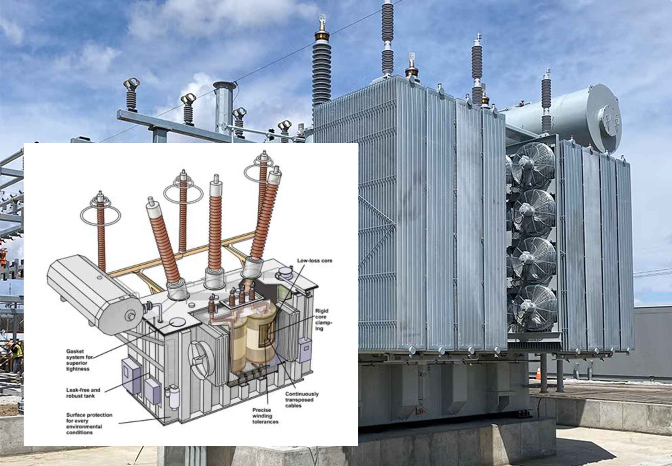
The foundational element of any transformer, regardless of its type, is the core and coil assembly. This assembly is where the magnetic and electrical energy conversion takes place.
The Core
The core is the transformer’s magnetic body, constructed from stacked, thin metal sheets called laminations. The primary purpose of the iron core is to channel the magnetic flux generated by the current flowing through the primary winding, ensuring that the maximum possible flux links the secondary winding.
The Coils (Windings)
The windings are manufactured from either copper or aluminum conductors and are separated by layers of insulation. The conductors are formed with high precision around a large spool. The specific number of turns in each winding is directly dependent on the required voltage ratio of the transformer. In a typical configuration, the low-voltage coil is positioned closest to the iron core, and the high-voltage coil encloses the low-voltage coil. Connection points are welded at the ends of each winding and brought out to allow for the installation of cables or busbars.
Voltage Regulation: Voltage Taps
Voltage taps are optional components installed on the primary windings to provide a means of regulating the transformer’s output voltage. This regulation is achieved by altering the number of turns in the winding, which consequently changes the transformer’s turns ratio. Taps typically feature five positions (often labeled A, B, C, D, E, or 1 through 5). The tap setting can be changed either by physically moving jumpers between terminals on the winding or by using a selector switch. It is critical to note that these taps are typically de-energized tap changers, meaning they cannot be moved while the transformer is energized.
Liquid-Filled Transformers
Liquid-filled transformers are characterized by their core and coil assemblies being immersed in an insulating liquid. This liquid serves a dual, fundamental purpose:
- Insulation: It is the primary element of the transformer’s insulating system.
- Cooling: It transfers heat away from the windings to be dissipated by external components such as cooling fins, the tank surface, or radiators.
Sufficient liquid immersion is essential to prevent overheating or electrical flashover of energized, current-carrying components. Conversely, an excessively high liquid level can lead to an overpressure condition inside the tank as temperatures fluctuate. A positive seal may be maintained using an inert-gas system, where the tank is slightly pressurized with an inert gas like nitrogen.
Types of Insulating Liquids
Technicians are likely to encounter four primary types of insulating liquids in the field. It is a critical safety and operational requirement that these liquids should not be mixed, and manufacturers’ instructions and Safety Data Sheets must be strictly followed.
| Insulating Liquid Type | Base Material | Key Characteristics | Regulatory Note |
| Mineral Oils | Petroleum-based | Traditional, widely used insulating and cooling medium. | Generally safe, but flammable. |
| Natural Esters | Renewable natural sources | Biodegradable, higher flash point than mineral oil, improving fire safety. | Increasingly used as an environmentally friendly alternative. |
| Askarel | Polychlorinated Biphenyls (PCBs) | Identified by various brand names; highly toxic substance. | Subject to strict government regulation; knowledge of PCB regulations is necessary due to potential contamination in older units. |
| Silicone or Stabilized Hydrocarbon Liquids | Synthetic or modified hydrocarbons | Less flammable than mineral oil, offering enhanced fire resistance. | Used in applications where fire safety is a primary concern. |
Liquid Preservation Techniques
Preservation techniques are employed to minimize the exposure of the insulating liquid to the atmosphere, which can degrade its properties. The following are common construction types:
| Preservation Technique | Description |
| Free Breathing | The liquid is open to the atmosphere, allowing air and moisture exchange. |
| Restricted Breathing | Open to the atmosphere, but through the use of dehydrating compounds (e.g., a desiccant breather) to limit moisture ingress. |
| Conservator or Expansion Tank | A separate tank is installed above the main tank; exposure to air is limited to the liquid within this conservator tank. |
| Sealed Tanks | A gas space above the liquid acts as a cushion to absorb internal pressure changes due to temperature variations. |
| Gas–Oil Seal | Exposure to air is limited to the oil in an auxiliary tank, which acts as a barrier. |
| Inert Gas | The gas space above the liquid is maintained under positive pressure by a continuous supply of inert gas, typically from a nitrogen cylinder. |
Liquid Transformer Cooling Systems
Effective heat dissipation is paramount for transformer longevity. A transformer operating at just 10°C above its rated temperature can reduce its service life by 50%. Common methods for dissipating heat in liquid-filled transformers include:
| Cooling System Code | Description | Heat Dissipation Method |
| ONAN (Oil Natural, Air Natural) | Self-cooled | Heat is dissipated naturally by the tank surface and cooling fins or tubes. |
| ONAF (Oil Natural, Air Forced) | Forced-air cooled | Fans are used to force air over the cooling surfaces, augmenting the self-cooled rating. |
| OFAF (Oil Forced, Air Forced) | Forced-oil cooled/Forced-air cooled | An oil pump circulates the oil through a heat exchanger, which is then cooled by forced air from fans. |
| OFWF (Oil Forced, Water Forced) | Water cooled | Heat exchange is achieved by pumping water through a pipe coil installed either inside or outside the transformer tank. |
Dry-Type Transformers
Dry-type transformers operate using air or gas as the insulating and cooling medium, rather than liquid. They are generally categorized into two construction types: the open or ventilated dry-type and the sealed or closed-tank type. Maintaining a clean enclosure and clear surrounding area is essential for their operation.
Ventilated Dry-Type Construction
Ventilated dry-type transformers commonly utilize either varnish-impregnated or cast-coil construction.
Varnish Impregnation
In this method, the spaces between the conductor coverings and the turns of the electrical winding are thoroughly coated with varnish. The varnish is then cured to provide:
- Optimal insulating and thermal conducting properties.
- Imperviousness to moisture.
- Sufficient mechanical strength to resist fracture of the coating.
Cast Coil
Cast coil transformers are manufactured by combining the coils with a cast resin in a vacuum furnace, effectively “casting” them into a solid block. This manufacturing process results in a transformer that is:
- More resistive to heat.
- Less susceptible to fire.
Sealed Tank (Gas Insulated)
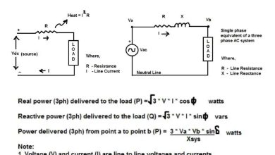
Sealed transformers are cooled and insulated by a high-dielectric inert gas, such as nitrogen or sulfur hexafluoride. The construction is fundamentally similar to a liquid-filled transformer, with the primary difference being the substitution of the liquid medium with the inert gas. Gas Insulated Transformers (GIT) are often preferred for use in urban areas where space is limited and safety is a critical consideration, as they are compact and cost-effective. The external cooling design concept for a GIT is nearly identical to that used for oil-filled transformers.