Transformer Turns Ratio and Polarity Testing: Principles, Procedures, and Safety
The Transformer Turns Ratio (TTR) test is a critical diagnostic procedure used to assess the integrity and performance of power transformers. It determines the ratio of the number of turns in one winding to the number of turns in another winding within the same phase. This test is essential for both acceptance testing of new or repaired transformers and maintenance testing to monitor the transformer’s condition over its operational life.
Purpose and Significance
The TTR test serves multiple vital functions in transformer assessment:
- Verification of Nameplate Data: During acceptance testing, the TTR confirms that the actual turns ratio aligns with the manufacturer’s specifications.
- Detection of Faults: Deviations in the ratio can indicate internal issues such as shorted turns, open windings, or improper internal connections.
- Polarity Determination: The TTR test is often performed in conjunction with the transformer polarity test, which establishes the vectoral relationships between the various windings. The polarity test is primarily an acceptance test, while the TTR test is used for both acceptance and maintenance.
Test Equipment
The preferred instrument for this procedure is a dedicated Turns Ratio Tester (TTR). If a TTR is unavailable, an approximation can be made by measuring the input and output voltages using high-accuracy voltmeters. These voltmeters must possess a minimum full-scale accuracy of 0.25 percent to ensure reliable measurements.
Testing Procedure and Tap Positions
A comprehensive TTR test requires measurements across all operational tap positions to ensure the transformer is functioning correctly under all operating conditions.
| Tap Type | Testing Requirement |
| No-Load Taps | The ratio must be determined for every no-load tap position. |
| Load-Tap Changer (LTC) | If the transformer is equipped with an LTC, the ratio must be measured at each LTC position. |
| Combined Taps | For transformers with both LTC and no-load tap changers, the ratio should be determined for each LTC position while the no-load tap changer is held at a single position, and vice versa, to ensure complete coverage. |
Safety Considerations
Safety is paramount when performing transformer testing. All personnel involved must be qualified to service high-voltage equipment. Before commencing any test, the following safety protocols must be strictly observed:
- De-energization: The transformer must be completely de-energized.
- Lockout/Tag-out (LOTO): Follow all relevant safety procedures, including OSHA’s LOTO protocols, to ensure the transformer remains isolated from all power sources.
- Winding Verification: Every winding must be checked to confirm it is de-energized.
Test Connections and Setup
The connection of the TTR test set is based on matching parallel vectors to ensure correct phase alignment. While specific setup procedures vary by manufacturer, all TTR test sets utilize at least two high-voltage leads (H-leads) and two low-voltage leads (X-leads).
General Setup Guidelines
- Isolation: Ensure all transformer terminals are disconnected from the line and load. Ground connections may be left in place if desired.
- Test Set Verification: Perform preliminary checks to verify the TTR test set’s performance, as detailed in the user manual.
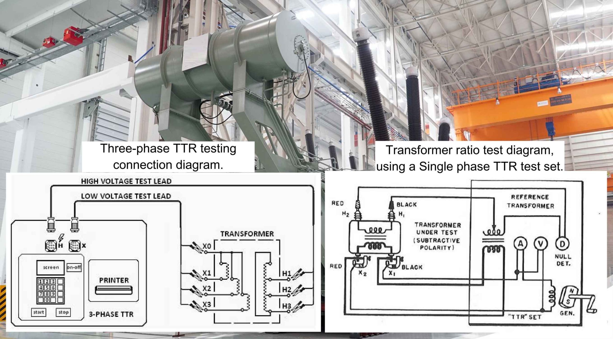
Single-Phase Models
- Connect the exciting leads (X1 and X2) to the lower-voltage winding of the two windings being compared.
- Match transformer polarity by connecting the H1 secondary lead to the higher-voltage terminal corresponding to the X1 connection.
- Connect the H2 lead to the other high-voltage terminal.
- Where both windings are grounded on one side, connect X1 and H1 to the grounded sides.
- Always excite the entire low-voltage winding.
- For polyphase transformers, repeat this procedure on each set of windings to be measured.
Three-Phase Models
- Connect the H0, H1, H2, and H3 test cables to the corresponding high-voltage winding terminals. Note that the H0 lead is not used for delta-connected windings.
- Connect the X0, X1, X2, and X3 test cables to the corresponding low-voltage winding terminals. Note that the X0 lead is not used for delta-connected windings.
- It is possible to test single-phase two-winding transformers using a three-phase TTR test set by utilizing only the H1, H2, X1, and X2 leads.
Acceptable Test Values
The results of the turns ratio test should not deviate by more than one-half percent (0.5%) from either the adjacent coils or the calculated ratio.
Test values that fall outside of this tolerance may indicate a serious issue, such as a shorted or open transformer winding. If an out-of-tolerance reading is obtained, the following steps should be taken before concluding a fault exists:
- Check all test set connections for proper contact and configuration.
- Perform a self-test on the TTR instrument.
- Retest the winding.
If the deviation persists after retesting, the transformer should be further investigated for internal faults.