Types of Motor Protection: Safeguarding Industrial Assets
Electric motors are the workhorses of modern industry, driving everything from pumps and compressors to conveyor belts and fans. Given their critical role, protecting these assets is paramount. Motor protection is not merely an optional feature; it is a fundamental requirement to prevent damage, ensure personnel safety, reduce costly downtime, and maintain stable, continuous plant operation. The primary goal of any motor protection scheme is to isolate the motor quickly when a fault occurs, thereby limiting the thermal and mechanical stresses that can lead to premature failure.
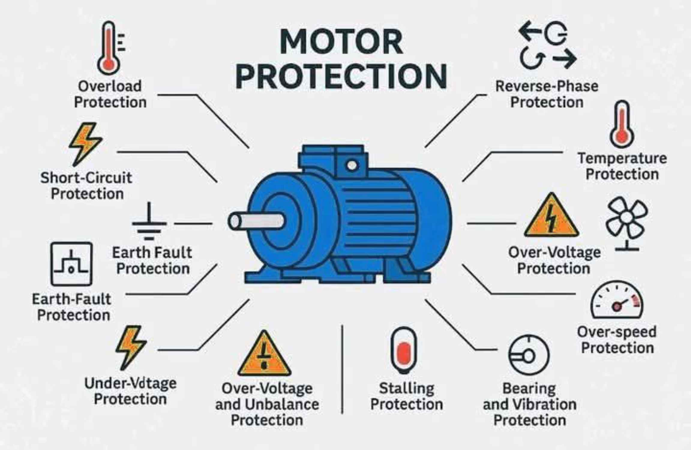
A comprehensive motor protection strategy addresses five main fault categories, each requiring a distinct protective mechanism.
1. Overload Protection
Overload protection is designed to safeguard the motor against overheating caused by excessive current draw over an extended period. This condition typically arises from mechanical issues (e.g., seized bearings, excessive load) or electrical problems (e.g., single-phasing). Prolonged overcurrent causes excessive heat generation, the primary cause of insulation breakdown and motor failure.
•Mechanism: The protection device monitors the motor current and estimates the thermal state of the windings. When the current exceeds the motor’s full-load ampere (FLA) rating for a specific duration, the device trips.
•Devices: This is typically achieved using thermal overload relays (bimetallic strips), electronic overload relays (which offer greater precision and adjustability), or built-in thermal sensors (such as RTDs or PTC thermistors) embedded directly in the motor windings.
•Trip Classes: Overload relays are classified by their trip time, as defined by standards like IEC 60947-4-1. These trip classes (e.g., Class 10, Class 20, Class 30) specify the maximum time the relay will take to trip at a multiple of the set current. For instance, a Class 10 relay is suitable for standard loads, whereas a Class 20 or 30 relay is required for high-inertia loads that require a longer starting time.
2. Short-Circuit Protection
Short-circuit protection is the high-speed defense against catastrophic faults. It protects the motor and its branch-circuit conductors from severe, instantaneous currents caused by insulation failure, such as a phase-to-phase or phase-to-neutral fault. These currents can be hundreds of times the motor’s normal operating current.
•Mechanism: This protection is designed to operate instantly to clear the fault before the massive current can cause extensive thermal and mechanical damage.
•Devices: Common devices include fuses, Molded Case Circuit Breakers (MCCBs), or Motor Circuit Protectors (MCPs) with instantaneous trip elements. The National Electrical Code (NEC) requires that the short-circuit protective device be sized to protect the motor and conductors from fault current while allowing the motor to start successfully.
3. Earth-Fault (Ground-Fault) Protection
Earth-fault protection detects leakage currents flowing from a phase conductor to the ground. This fault is hazardous as it can compromise the motor winding insulation and pose a severe safety hazard to personnel (touch potential).
•Mechanism: The protection system typically uses a zero-sequence current transformer (CT) to monitor the vector sum of the currents in the phase conductors. In a healthy system, this sum is zero. A non-zero sum indicates current flowing to the ground.
•Devices: Earth-fault relays or Residual-Current Devices (RCDs) are used to detect these currents and trip the motor contactor. While short-circuit protection handles high-magnitude faults, ground-fault protection is often more sensitive, detecting low-level leakage currents that may not be large enough to trigger the short-circuit device but are still dangerous.
4. Under-Voltage Protection
Under-voltage protection is crucial because a significant drop in supply voltage can be just as damaging as an overcurrent. When the voltage drops, the motor attempts to maintain its required torque by drawing a proportionally higher current.
•Mechanism: The protective relay monitors the supply voltage and trips the motor if the voltage remains below a predetermined threshold (e.g., 80% of nominal voltage) for a set time.
•Devices: Under-voltage relays or under-voltage releases integrated into contactors are used. This protection prevents the motor from overheating due to excessive current draw and also prevents contactor “chatter,” which can damage the control circuit.
5. Over-Voltage Protection
Over-voltage protection safeguards the motor’s insulation and windings against excessive voltages that can cause premature dielectric breakdown. Over-voltage conditions can arise from switching surges, lightning strikes, or poor regulation in the power system.
•Mechanism: The protection system monitors the supply voltage and trips the motor if the voltage exceeds a safe upper limit.
•Devices: Over-voltage relays are used for system-level protection. At the same time, surge protectors or surge arresters are installed at the motor terminals to divert high-energy transient spikes (such as those from lightning) away from the motor windings and safely to ground.
Summary of Motor Protection Types
The following table summarizes the five essential types of motor protection, their primary fault targets, and the typical devices used:
| Protection Type | Fault Target | Primary Consequence of Failure | Typical Devices |
| Overload | Excessive current (prolonged) | Overheating, insulation breakdown | Thermal/Electronic Overload Relays, RTDs |
| Short-Circuit | High-magnitude phase-to-phase fault | Catastrophic mechanical/thermal damage | Fuses, MCCBs, Motor Circuit Protectors |
| Earth-Fault | Leakage current to ground | Personnel safety hazard, winding damage | Earth-Fault Relays, RCDs, Zero-Sequence CTs |
| Under-Voltage | Low supply voltage | Overheating due to high current draw | Under-Voltage Relays/Releases |
| Over-Voltage | Excessive supply voltage or transients | Dielectric breakdown of winding insulation | Over-Voltage Relays, Surge Arresters |
By implementing a coordinated protection scheme that addresses all five of these fault types, engineers ensure the longevity of their motors and the uninterrupted, safe operation of their industrial processes.
References
[1] International Electrotechnical Commission (IEC). IEC 60947-4-1, Low-voltage switchgear and controlgear – Part 4-1: Contactors and motor-starters – Electromechanical contactors and motor-starters. Defines trip classes for overload relays.
[2] National Fire Protection Association (NFPA). NFPA 70: National Electrical Code (NEC). Article 430, Motors, Motor Circuits, and Controllers.