Power Cables Single-Point Bonding in High-Voltage Cable Systems
Methodology
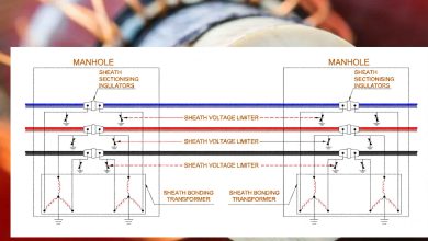
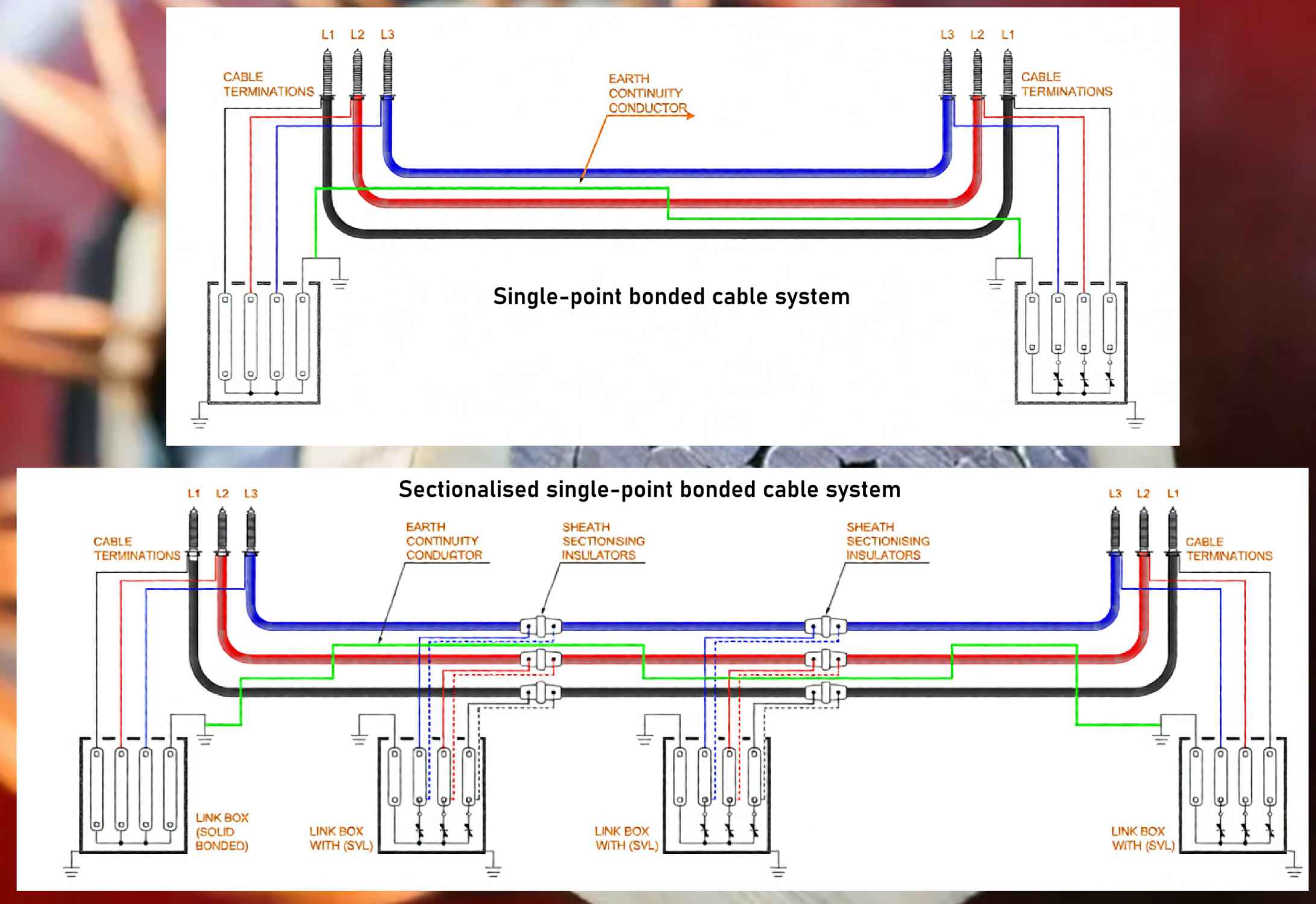
Single-point bonding is a cable sheath earthing configuration in which the sheaths of all three phases are interconnected and solidly earthed at one terminal. In contrast, the opposing terminal remains isolated from ground (see Figure 3). This method is characteristically applied to circuits of limited length. For extended routes, an adaptation known as multiple single-point bonding is employed. In this scheme, the three sheaths within a defined section are bonded and grounded to an Earth Continuity Conductor (ECC) at one end, while being terminated through Sheath Voltage Limiters (SVLs) at the other. This pattern is replicated sequentially along the cable route.
Application
Single-point bonded systems are widely utilized in high-voltage transmission networks, serving as a principal alternative to multi-point bonding. Their application is particularly prevalent in substation environments with relatively short cable routes where the implementation of cross-bonding is economically non-viable.
Advantages
- Enhanced Current Rating: By eliminating the formation of a closed electrical loop, this method precludes the induction of circulating currents in the sheath. Consequently, associated resistive losses are removed, permitting a higher permissible current rating for the cable conductor.
- Economic Efficiency: The requirement for only a single continuous cable length per phase renders this an economically favorable solution for suitable applications.
- Elimination of Longitudinal Sheath Currents: The absence of a continuous metallic sheath path prevents the flow of longitudinal currents, thereby nullifying circulating current losses. (Note: Non-circulating eddy current losses within the sheath material persist.)
Disadvantages
- Sheath Voltage Rise: A standing voltage is induced longitudinally along the sheath, proportional to the conductor current, cable length, and inter-phase spacing. This voltage increases linearly with distance from the earthed point.
- Cost Implications of Mitigation: To limit this voltage to safe levels, an Earth Continuity Conductor (ECC) must often be installed in parallel with the cable route, introducing significant additional material and installation costs.
- Safety and Insulation Requirement: The isolated sheath end must be meticulously insulated to prevent hazardous exposure to the induced standing voltage, imposing ongoing maintenance obligations.
Design Considerations
The primary design constraint is the sheath standing voltage at the isolated end, which dictates the maximum permissible section length. This voltage must be calculated and limited to a safe touch potential, typically between 35 V and 400 V, as governed by national safety standards.
Effective insulation of the sheath from earth is critical along its entire isolated length. Where anticipated transient overvoltages (e.g., from switching or faults) exceed 75% of the sheath insulator’s Basic Insulation Level (BIL), the installation of a Sheath Voltage Limiter (SVL) between sheath and earth at the open end is mandatory for protection.
An ECC is generally required unless both cable terminals share a common low-impedance earth. To minimize its own induced voltage, the ECC should be centrally transposed with respect to the phase conductors. Its geometric placement relative to the phases must be carefully engineered to ensure effective voltage limitation.