Ground Fault Indicators in MV Distribution Networks: Function and Application
Ground fault indicators (GFIs), also known as earth fault indicators or fault passage indicators (FPIs), are critical diagnostic instruments in medium-voltage (MV) distribution systems. Their primary function is to rapidly localize single-phase-to-ground faults, thereby significantly reducing outage duration and expediting system restoration. By providing a local visual or a remote electronic signal upon detection of fault current, these devices effectively delineate the faulted section of a network. This capability minimizes manual patrol requirements, enhances crew safety by reducing exposure to fault-chasing, and improves system reliability metrics, such as the System Average Interruption Duration Index (SAIDI).
1. Operational Principle and Distinction from Protective Devices
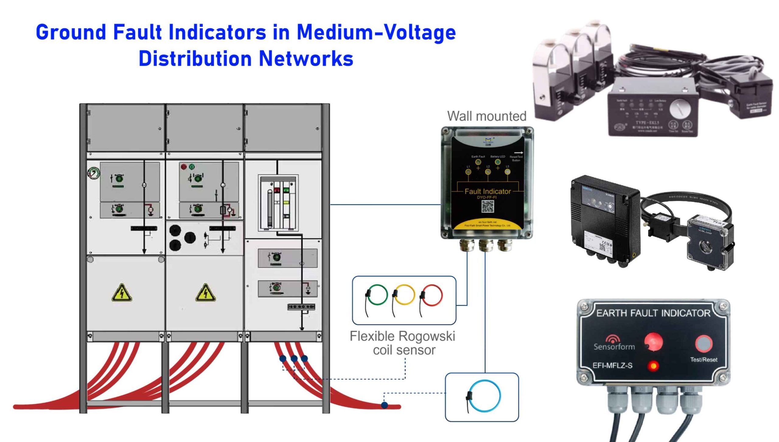
A GFI is a monitoring and signalling device typically installed on overhead lines, within cable networks, or integrated into switchgear. It operates by sensing the distinctive electromagnetic field or current imbalance associated with a ground fault, subsequently activating a mechanical flag and/or light-emitting diode (LED) indicator. Advanced units may also communicate a trip signal to a supervisory control and data acquisition (SCADA) system. The fundamental logic is to demarcate the last healthy point upstream from the fault location, enabling crews to isolate the affected segment efficiently.
It is essential to distinguish GFIs from ground-fault circuit interrupters (GFCIs). The former are network operational tools designed for fault location in MV systems. At the same time, the latter are personnel protection devices used in low-voltage installations to interrupt circuits upon detection of leakage current.
2. Detection Methodologies
Detection mechanisms are contingent upon system grounding. In solidly grounded networks, GFIs typically respond to a magnitude-based increase in zero-sequence current. For isolated or resonant-earthed (Petersen coil) systems, detection often relies on sensitive measurement of the residual current or zero-sequence voltage, necessitating more sophisticated algorithms to discriminate fault conditions from capacitive discharge transients. Standard sensor technologies include Rogowski coils, current transformers (CTs) for panel-mounted units, and clamp-on magnetic sensors for overhead line applications.
3. Utility Rationale for Deployment
Several operational benefits justify the implementation of GFIs:
- Enhanced Restoration Speed: Direct reduction in fault-finding time, leading to lower SAIDI and Customer Average Interruption Duration Index (CAIDI).
- Improved Personnel Safety: Minimizes the need for crews to patrol energized lines near persistent faults.
- Informed Switching Decisions: Remote-signalling variants provide system operators with real-time fault-location data, improving switching accuracy and situational awareness.
4. Typology and Selection Criteria
GFIs are categorized by installation context and functionality:
- Overhead Line Indicators: Feature robust, clamp-on designs with high-visibility targets; may incorporate wireless communication.
- Underground/Switchgear Indicators: Panel-mounted devices with local indication (LEDs, flags) and often provision for dry contacts or serial communication (e.g., RS-485/Modbus).
- Combined Fault Indicators: Detect both phase-to-phase short circuits and phase-to-ground faults.
Selection requires careful consideration of multiple factors:
- System Grounding: Must align with the detection algorithm (directional/non-directional, sensitivity settings).
- Load Profile & Settings: Pickup current and timing must be coordinated to avoid nuisance operations from intrush currents or switching transients.
- Installation Environment: Dictates enclosure rating (e.g., IP65), temperature tolerance, and mean time between failures (MTBF).
- Indication & Reset Methodology: Options include local manual reset, time-delayed auto-reset, or remote command reset.
- Communication Requirements: Integration needs ranging from local-only indication to SCADA connectivity.
5. Exemplar Product: The Lodestar PT2 Indicator
As a representative design, the Lodestar PT2 is a panel- or wall-mount combined short-circuit and earth-fault indicator rated for 6–35 kV systems. Its key specifications include:
- Sensing: Rogowski-coil based.
- Sensitivity: Adjustable phase-to-ground pickup from 10 A.
- Indication: Ultra-bright LED paired with a mechanical flag.
- Reset Modes: Manual, time-based, or external command.
- Robustness: IP65 enclosure, MTBF ≥110,000 hours.
- Auxiliary Power: Options for 110 V DC / 220 V AC-DC, with lithium battery backup.
For SCADA integration, the related PRO variant adds an RS-485 (Modbus) interface. This profile demonstrates alignment with standard requirements for MV switchgear applications.
6. Application Guidelines
- Sensitivity Tuning: Settings must be tailored to the network’s grounding scheme. Resonant-earthed networks often require lower pickup thresholds and may benefit from directional logic.
- Strategic Placement: Devices should be installed at strategic segmentation points (e.g., feeder origins, major junctions, cable taps) to bracket fault zones effectively.
- Procedure Integration: Reset logic (auto or manual) must be documented and coordinated with standard switching and restoration procedures to maintain indicator readiness.
7. Frequently Inquired Technical Points
- GFI vs. GFCI: As noted, these are distinct device classes with different purposes, standards, and voltage ratings.
- Performance in Resonant-Earthed Systems: Feasible but requires careful device selection and configuration to ensure reliable operation amid low fault currents.
- Optimal Installation Points: For maximum effectiveness, install at points that logically divide the network into monitorable sections.
- SCADA Integration: Many modern panel-mount GFIs support integration via dry contacts or serial communication protocols.
- Reference Design: Products such as the Lodestar PT2 provide a concrete benchmark for technical specification and procurement evaluation.